Assembly Guide - 8 - Electrical components
2.8 Electrical components
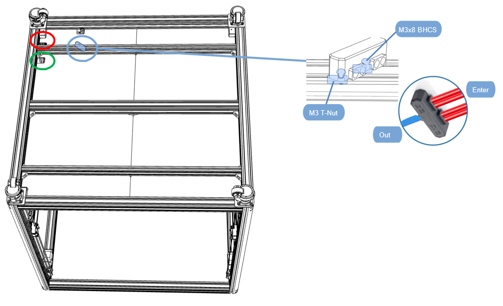
2.8.1 Hot bed line fixed
- Connect the four neutral wires from the bed heaters (the wires with the ferrule on the end) and insert into the screw terminal bus bar along with the Blue neutral wire that will go to the electronics enclosure;
- And use screws to fix the wiring terminal to the profile;
- The hotbed power wire and motor wire pass through the hole in the red frame;
- Complete the assembly together with the reference wiring diagram
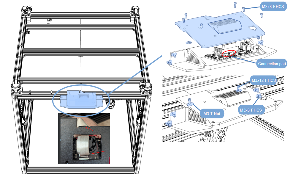
2.8.2 Display installation
- The display has been assembled, and the back cover needs to be removed first;
- Insert one end of the gray cable into the red area on the drawing;
- Tighten the screws and install it on the profile, centering it;
Display cable fixing
- Install a magnetic ring at each end of the display screen cable
- The gray cable of the display screen is fixed along the profile. The screws are tightened
- One end of the gray display cable passes through the hole in the green frame;
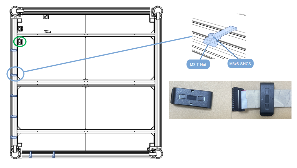
NOTE: Note where the cables pass through.
2.8.3 Electric box installation
- Tear off the protective paper on both sides of the acrylic board;
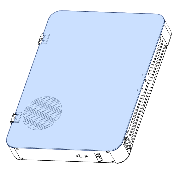
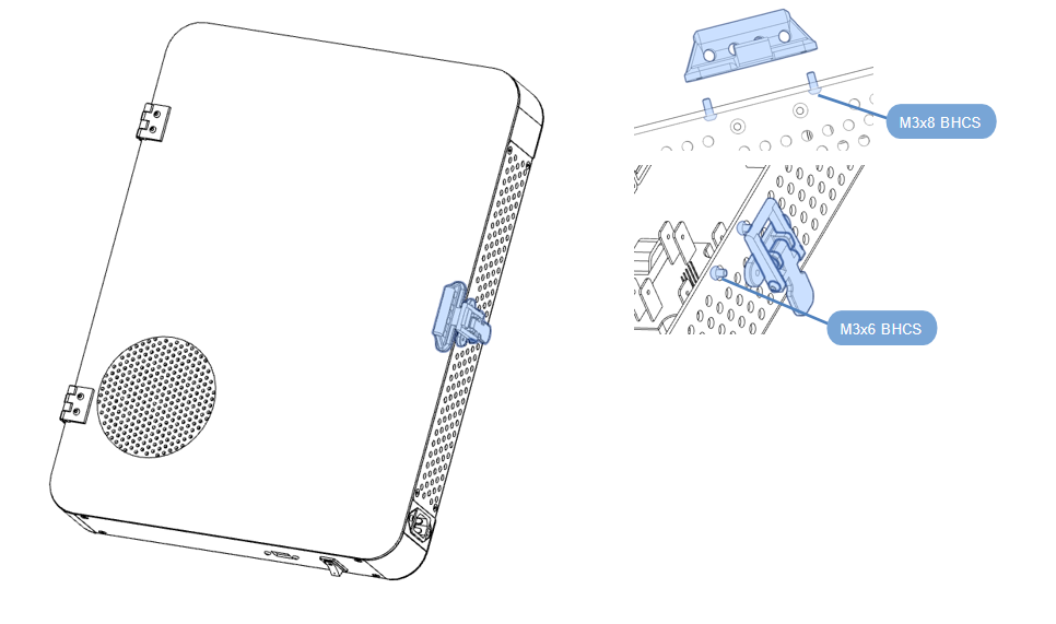
Electric box lock installation
- Assemble according to the diagram;
- Install the handle and lock inside the electrical box;
Electric box fixing
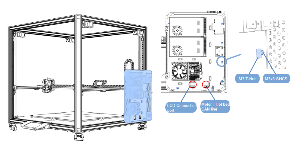
- Secure the electrical box to the right side of the frame via 6-SHCS M3x8;
- Pass the display screen, motor, heat bed, and CAN board wires through the window and connect them to the main board;
- Refer to the wiring diagram for the installation position;
2.8.4 Line wiring
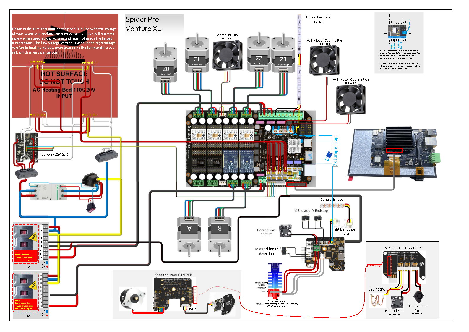
Version 1: Spider Pro
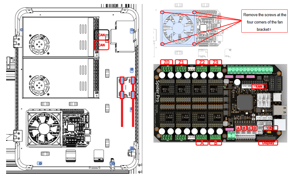
- First remove the fan and its bracket;
- Pass the display screen, motor, heat bed, and CAN board wires plug into the motherboard;
No. | 1 | 2 | 3 | 4 | 5 | 6 |
|---|---|---|---|---|---|---|
Motor serial number | Z0 | Z1 | Z2 | Z3 | A | B |
Motherboard serial number | M0 | M1 | M2 | M3 | M6 | M7 |
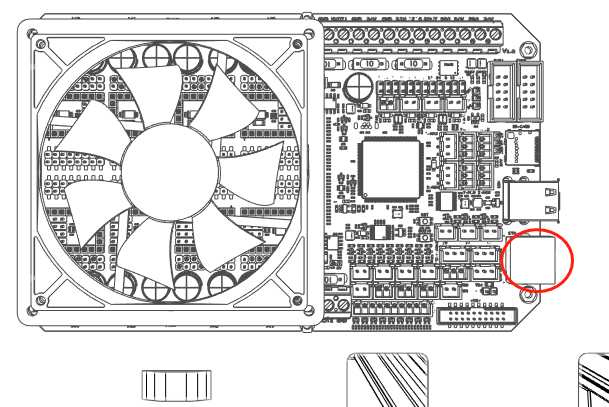
- Need to stick the conductive tape on the display cable to the metal shell of the network cable port.
NOTE: Make sure there is a magnetic ring on each end of the display gray cable.These are to enhance the anti-interference ability of the control circuit.
Wiring Diagram
File Links: Here
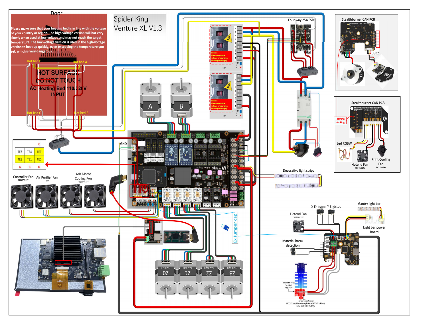
Version 2: Spider King
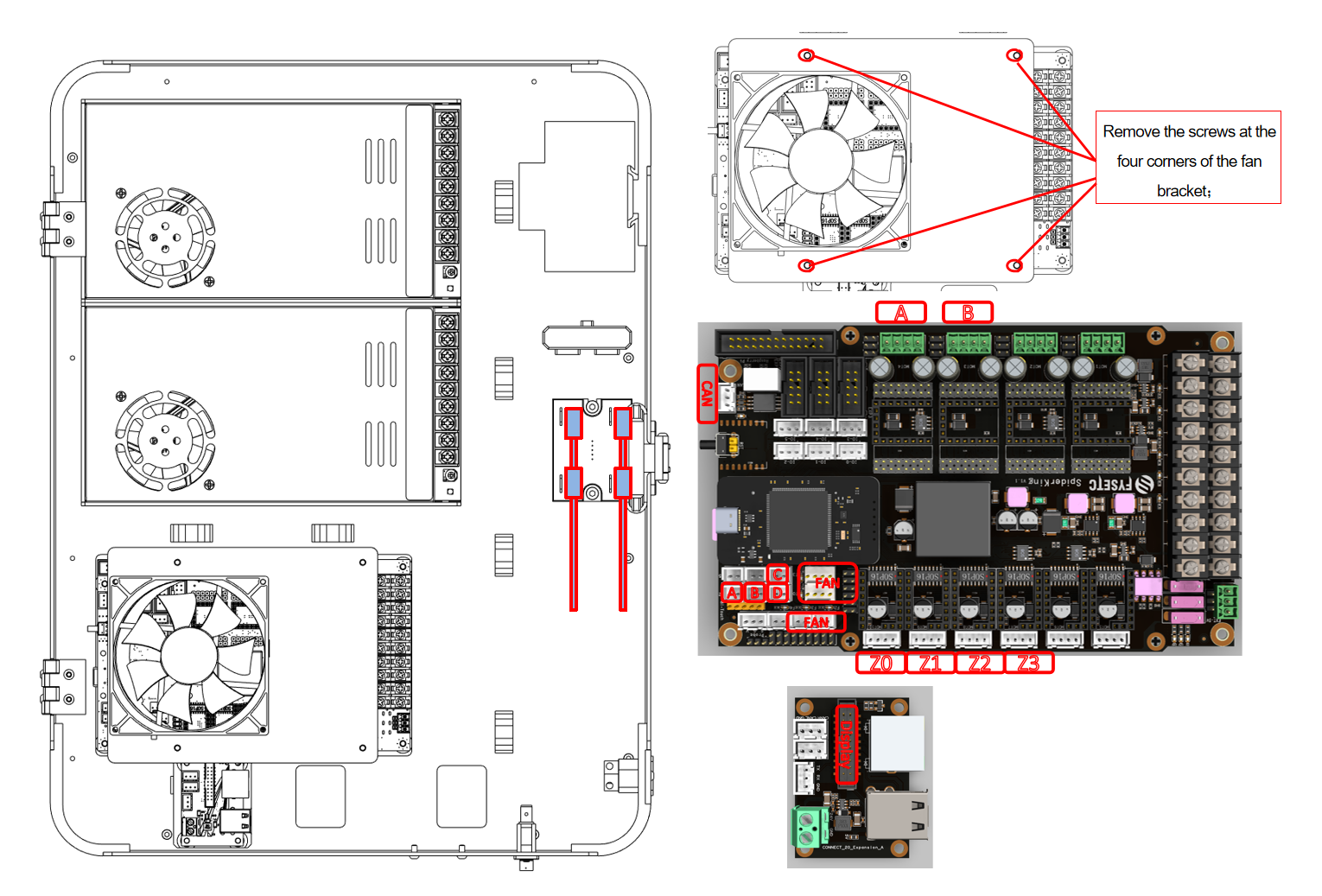
- First remove the fan and its bracket;
- Pass the display screen, motor, heat bed, and CAN board wires plug into the motherboard;
No. | 1 | 2 | 3 | 4 | 5 | 6 |
|---|---|---|---|---|---|---|
Motor serial number | Z0 | Z1 | Z2 | Z3 | A | B |
Motherboard serial number | M0T10-E4 | M0T9-E3 | M0T8-E2 | M0T7-E1 | M0T4-Z | M0T3-Y |
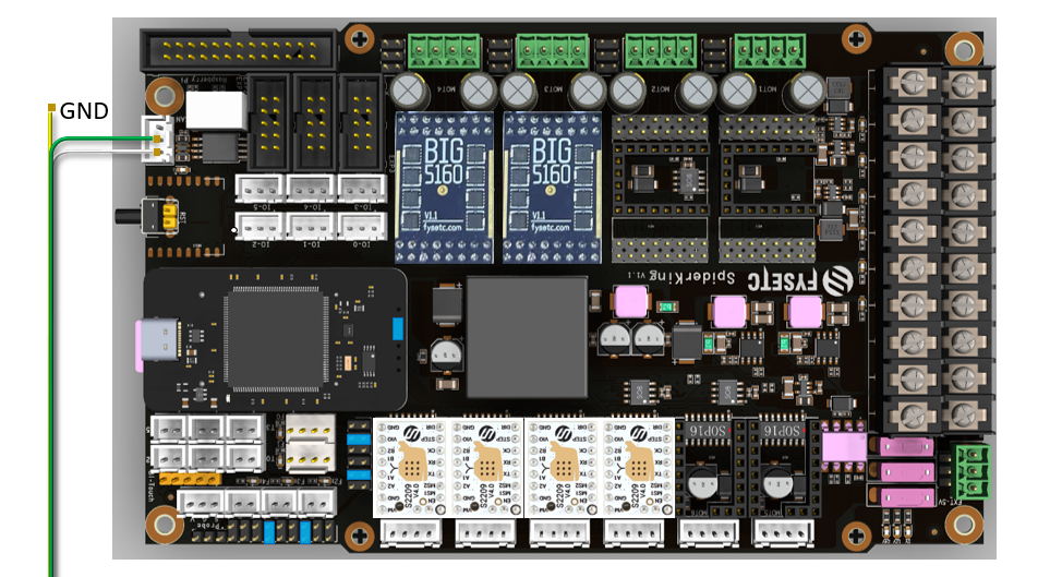
- The GND of the CAN line needs to be removed and not connected.
NOTE: Make sure there is a magnetic ring on each end of the display gray cable.These are to enhance the anti-interference ability of the control circuit.
File Links: Here
Toolheads Knife Holder
Illustration
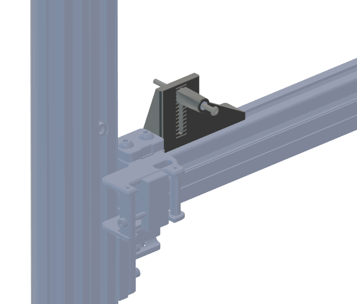
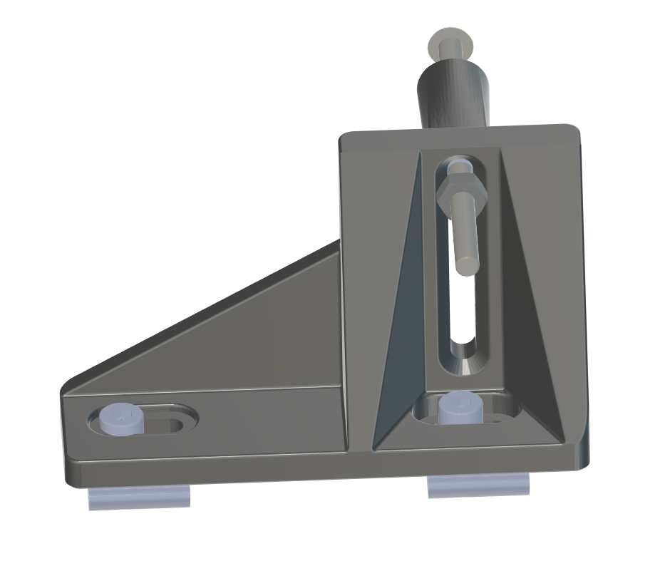
Cutting point on gantry
- 1x M3x30/M3x35 BHCS
- 2x Threaded Insert M3*5.0xH4.0
- 2x M3 Nut
- 2x M3x8 FHCS
- 2x M3 T-Nut
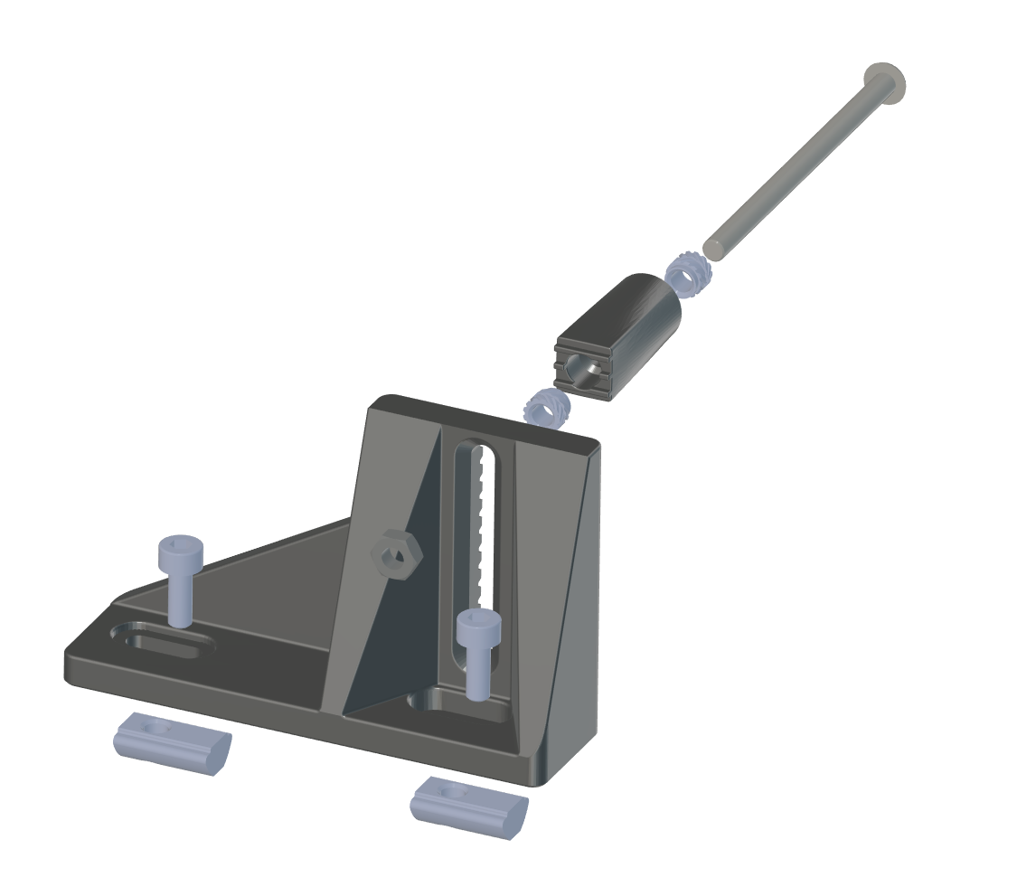
This chapter is assembled
Related articles
- ← Previous: Assembly Guide - 7 - Caster Assembly
- Assembly Guide overview
- Next: Assembly Guide - 9 - Rack and sealing acrylic →
Updated on: 03/08/2026
Thank you!