2.3 Gantry components
2.3 Gantry components
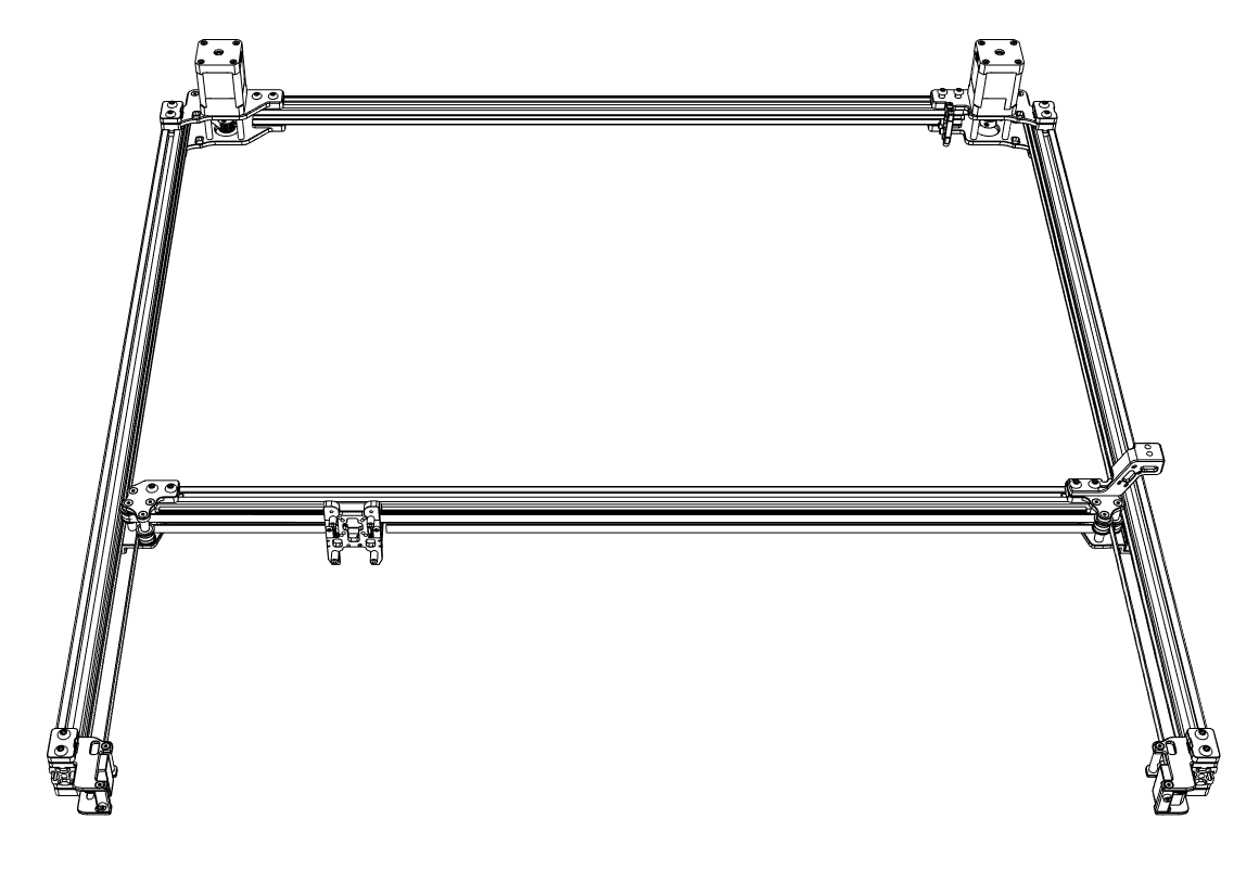
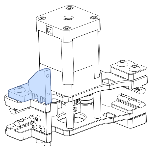
2.3.1 A Motor assembly
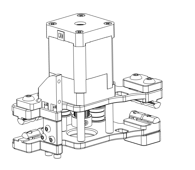
- Material preparation
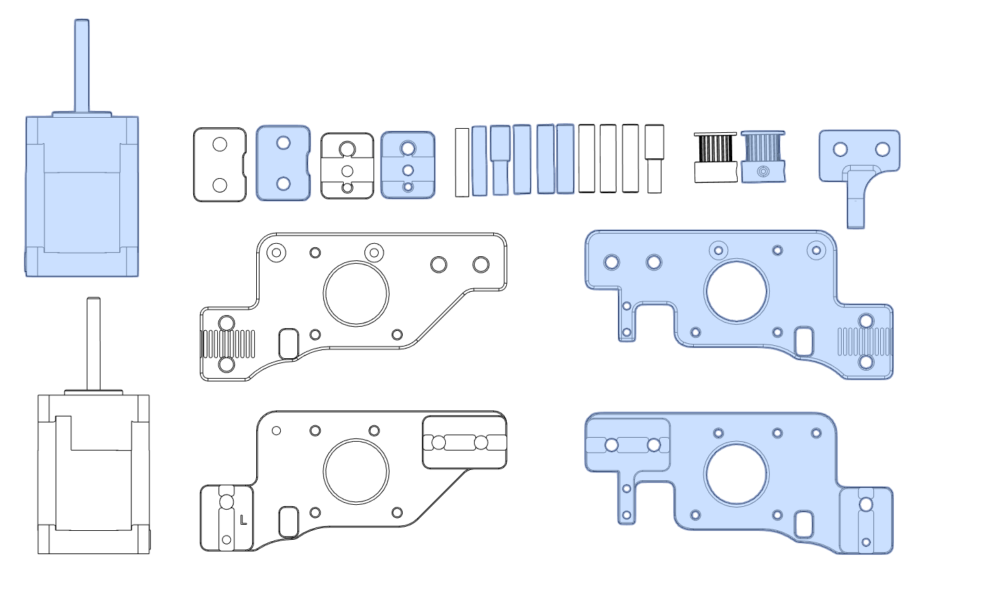
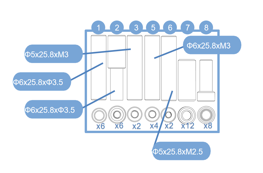
- Prepare the materials as shown in the figure;Use screws to assemble them;
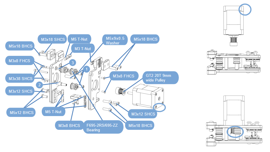
- Finally, use M3x38 screws to fix the motor;Pay attention to the direction of the motor wiring port.
- Check work:Compare your assembled part to the graphic shown here;Pay attention to the pulley orientation and alignment with the bearing stack ups.
2.3.2 B Motor assembly
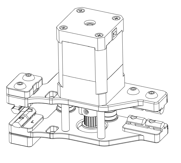
- Material preparation
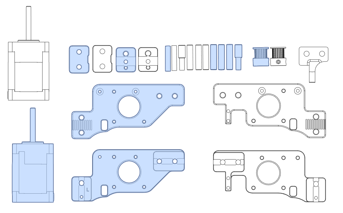
- Prepare the materials as shown in the figure;Use screws to assemble them;
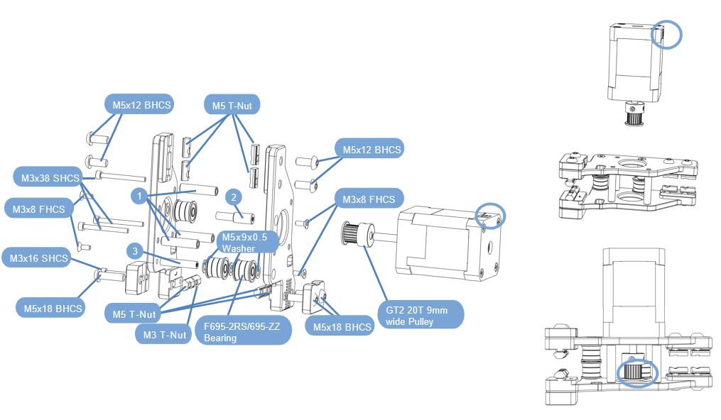
- Finally, use M3x38 screws to fix the motor;Pay attention to the direction of the motor wiring port.
- Check work:Compare your assembled part to the graphic shown here;Pay attention to the pulley orientation and alignment with the bearing stack ups.
2.3.3 XY joint component
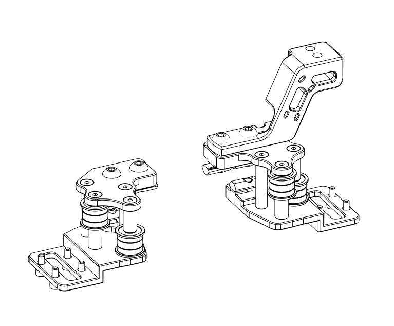
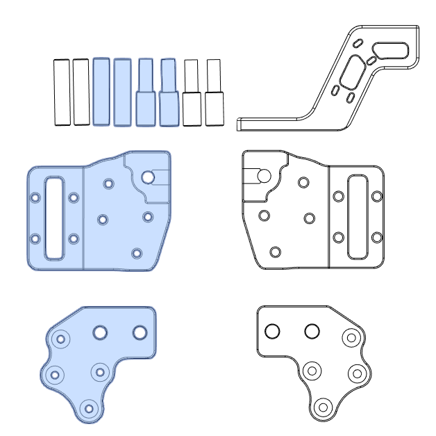
- Material preparation
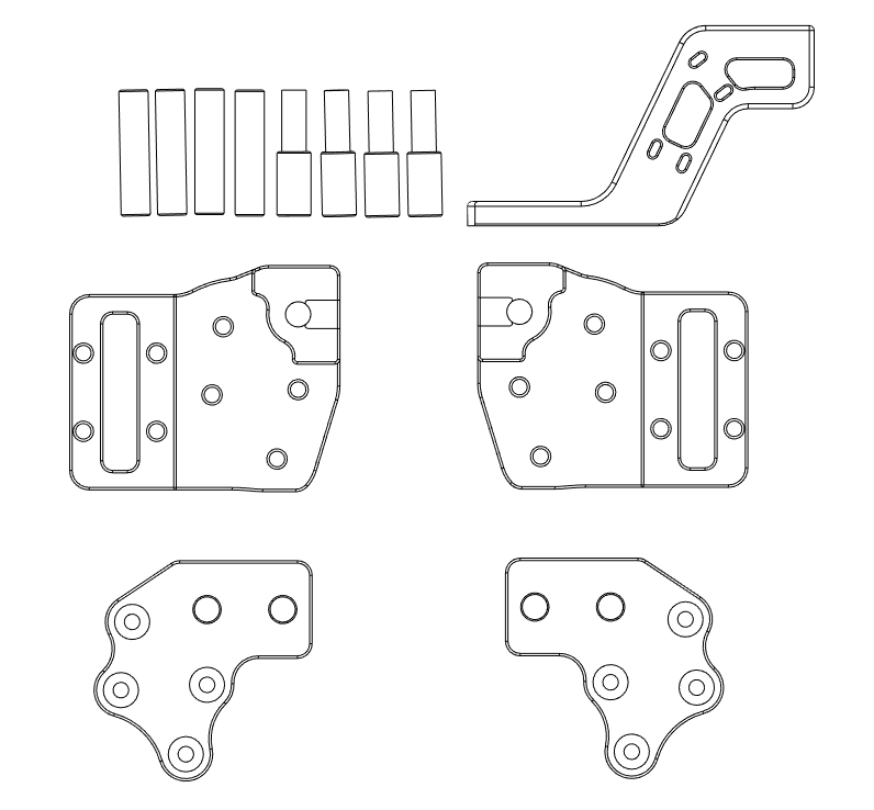
XY joint component-right
- Material preparation
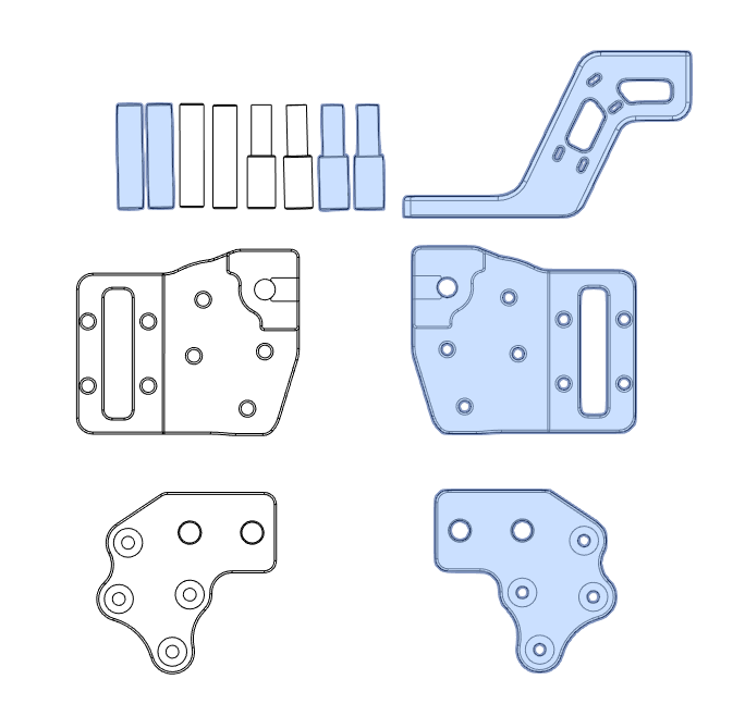
- Use screws to assemble them,Be careful not to tighten all the screws.
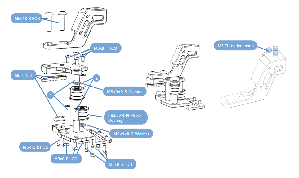
NOTE: The bearing can be replaced with a timing belt idler pulley.
XY joint component-left
- Material preparation
- Use screws to assemble them,Be careful not to tighten all the screws.
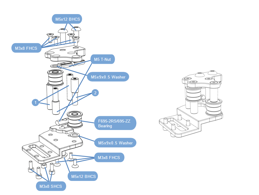
NOTE: The bearing can be replaced with a timing belt idler pulley.
2.3.4 AB Idler Assembly
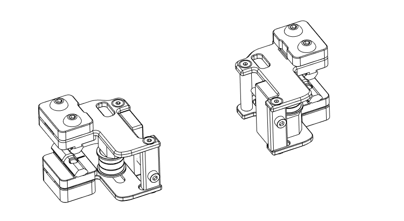
- Material preparation
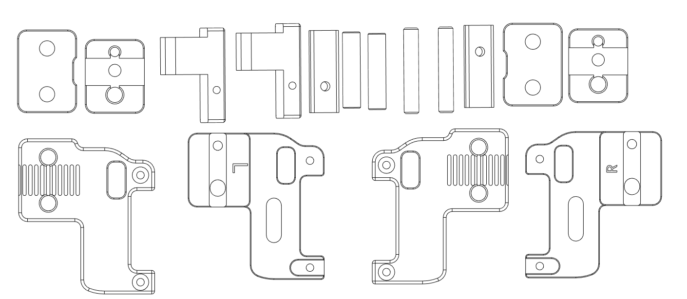
AB Idler Assembly-right
- Material preparation
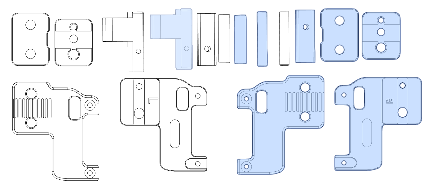
- Use screws to assemble them,Be careful not to tighten all the screws.
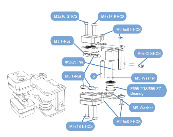
AB Idler Assembly-left
- Material preparation
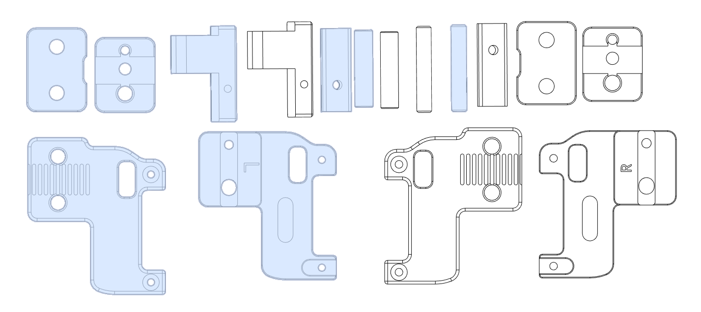
- Use screws to assemble them,Be careful not to tighten all the screws.
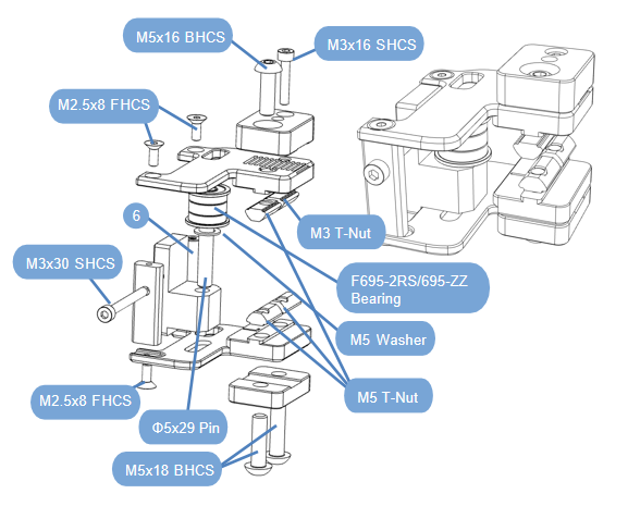
2.3.5 X-axis assembly
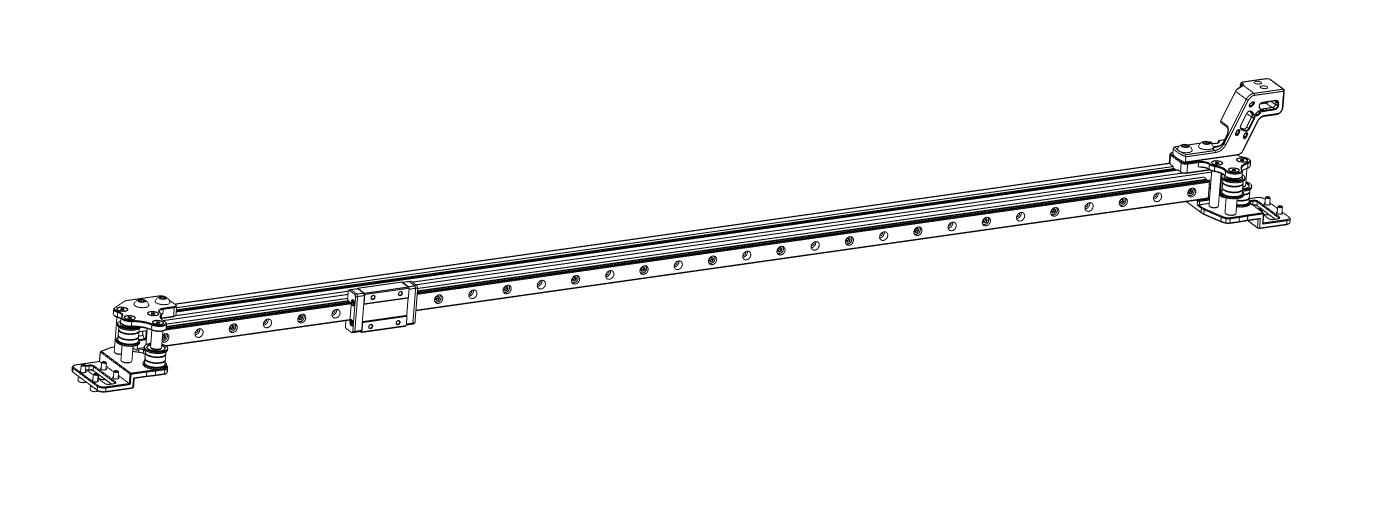
- Material preparation
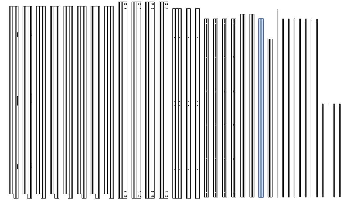
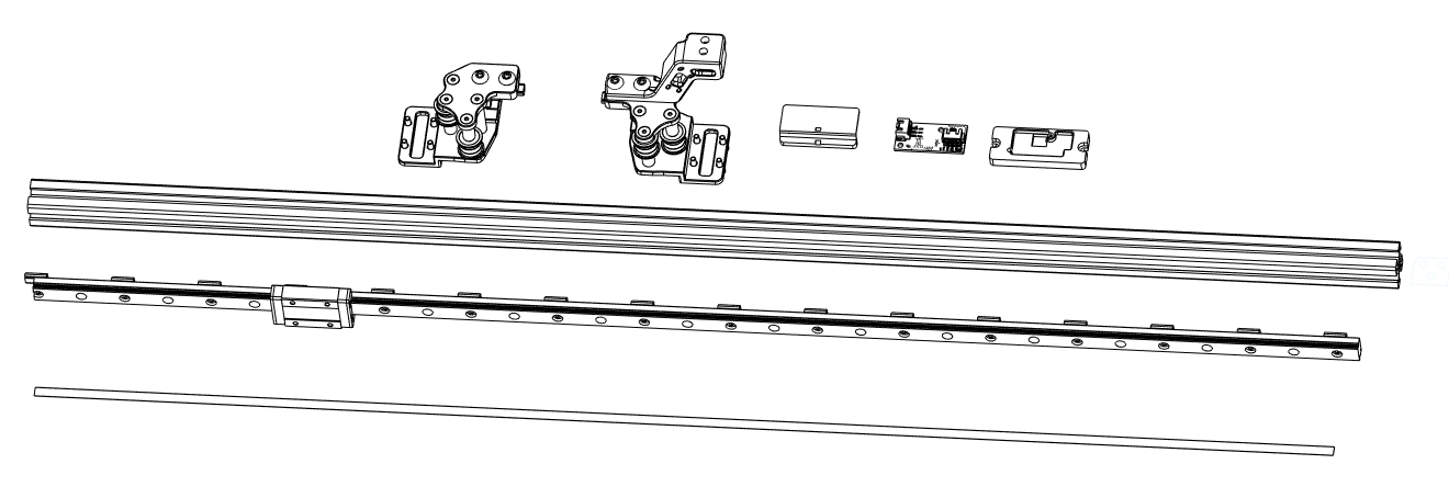
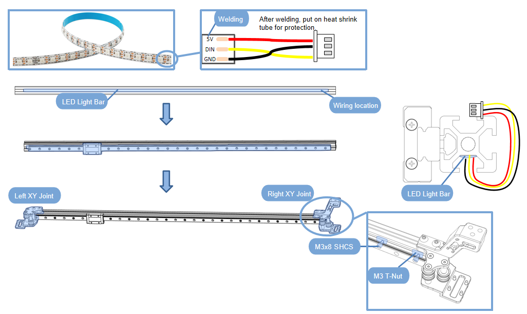
- First, solder the connecting wire at one end of the light strip (refer to the wiring diagram for wiring);Insert the light strip into the profile and stick it in the center;
- Install 1 Pcs linear guide MGN12H (length 765mm) on the side of the profile,Use M3x8 FHCS for fixing;
- Install the left/right XY joints on both sides of the profile and tighten the screws (make sure the light bar is on the bottom).
2.3.6 Y-axis assembly
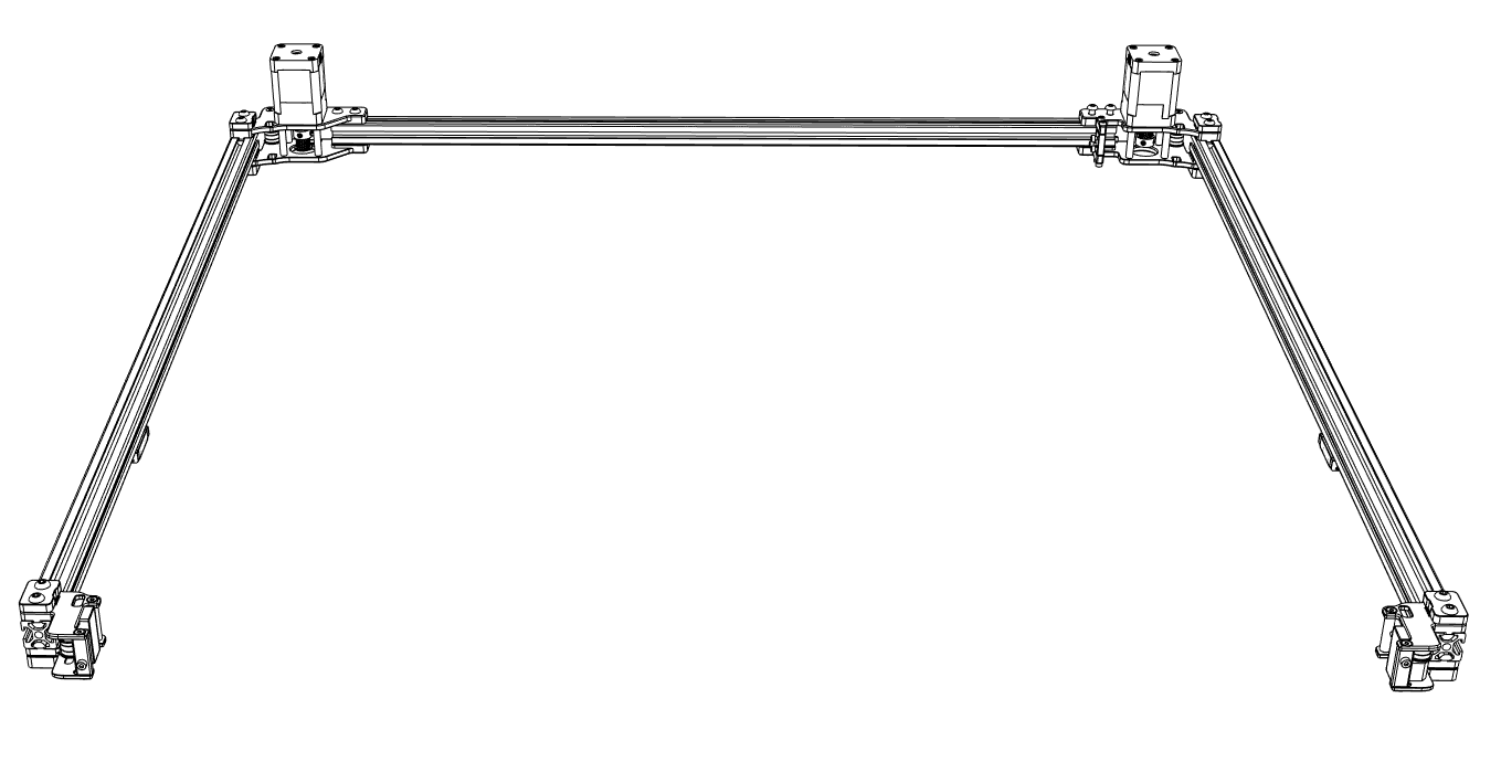
- Material preparation
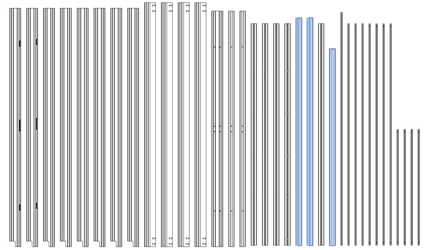
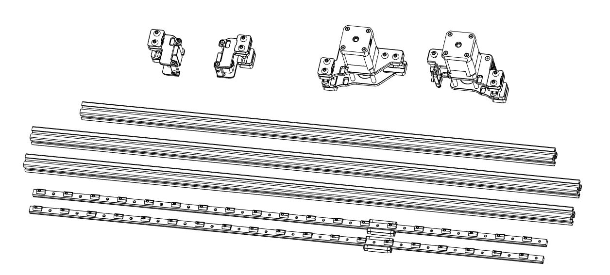
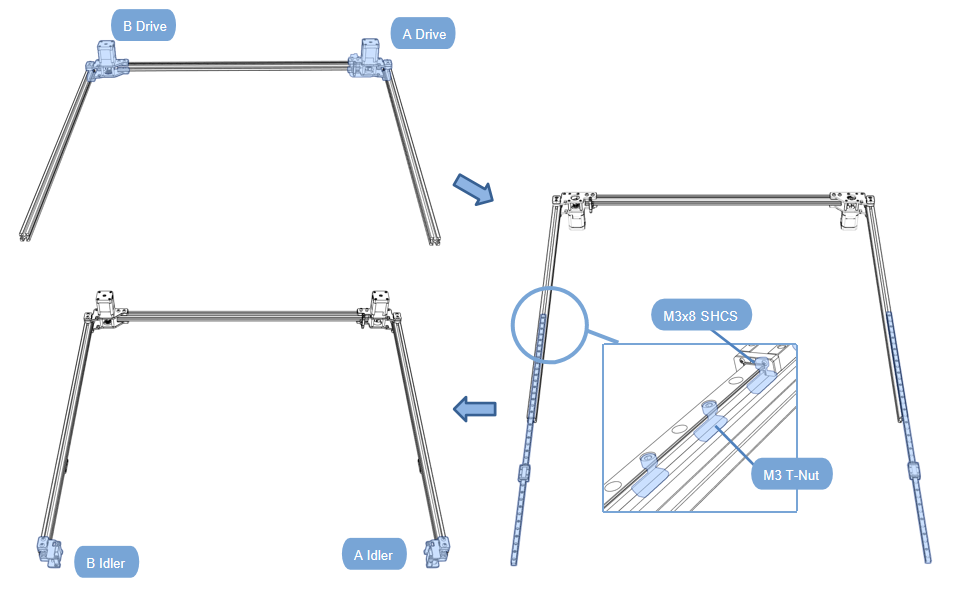
-First install the AB motors onto the profile (two profiles of the same length are Y);
- Insert the screwed guide rail from one end of the profile (MGN9H length 760mm,2PCS),Use M3x8 FHCS for fixing,locking screw;
- Finally install the AB idler assembly;Tighten all parts screws.
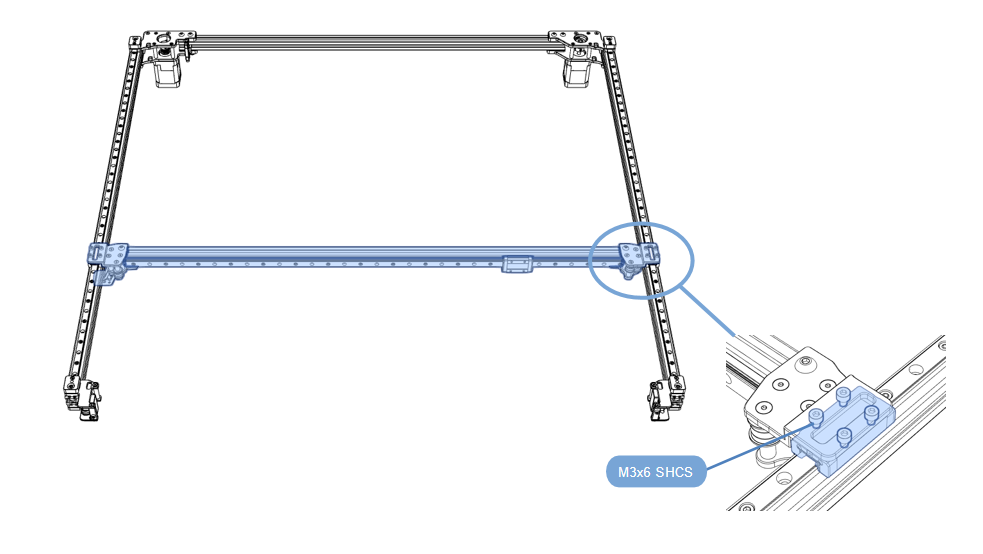
X-axis installation
- Install the previously assembled X-axis assembly onto the Y-axis assembly using the SHCS M3x6mm;
- Tighten all parts screws.
2.3.7 XY Belt, IDM bracket installation
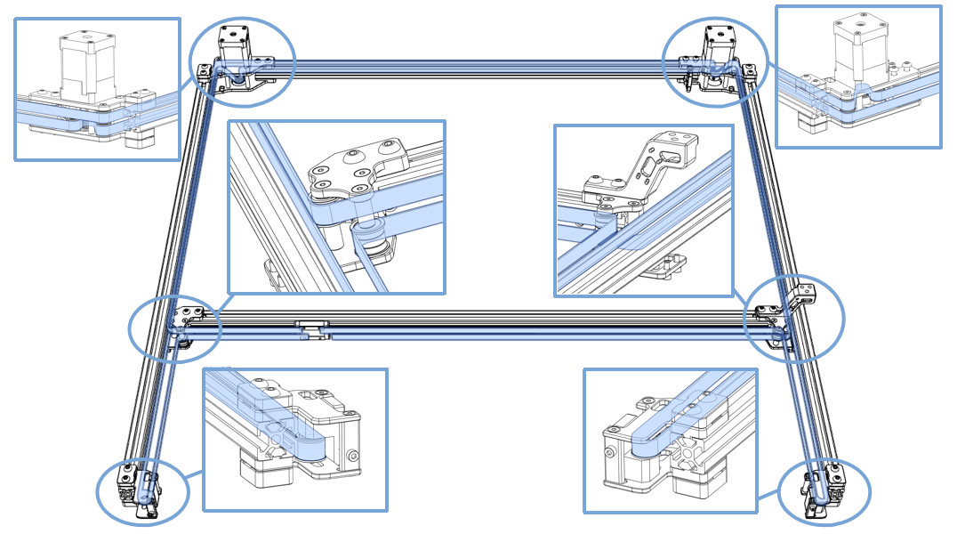
XY Belt
- Install the belt as shown;
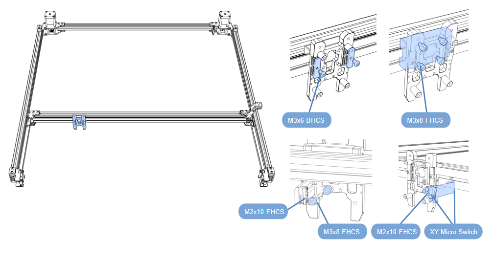
IDM bracket installation
- After the belt is put on, use Cartographer CNC toolhead to fix it, and use M3x6 BHCS to tighten the belt;Use M3x8 FHCS to fix the IDM ScannerCNC metal parts on the guide rail slide;
- Use M2x10 FHCS to fix 1 Pcs of micro switches on the printed part and 1 Pcs on the metal part;Install the micro switch print on the IDM ScannerCNC metal part and fix it with M3x8 FHCS;
Z-axis connector
- Material preparation
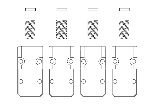
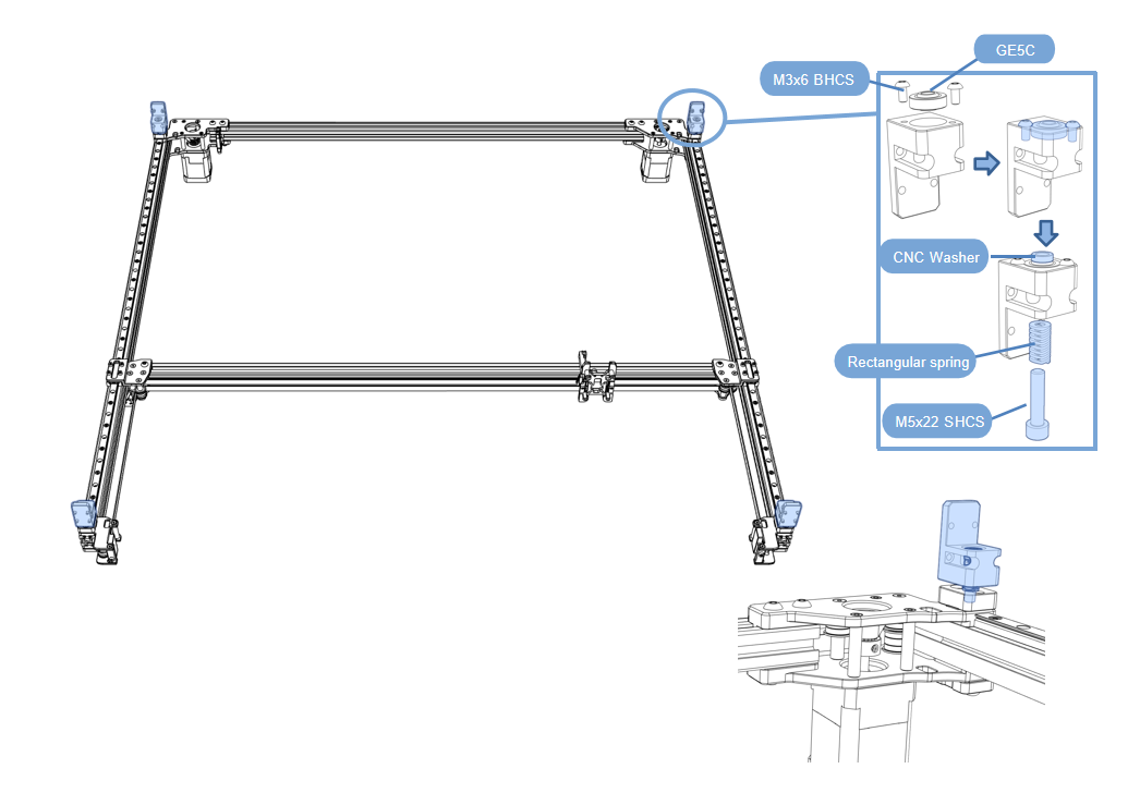
- First install the GE5C fisheye bearing in the connector slot and tighten the screws;
- Use SHCS M5x22 screws to pass through the spring and spacer and lock it to the frame.
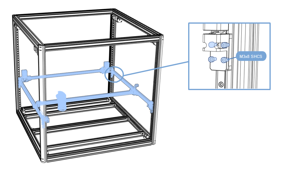
- Tilt the gantry into the frame,Use SHCS M3x8 screws to fix the gantry to the guide rails;
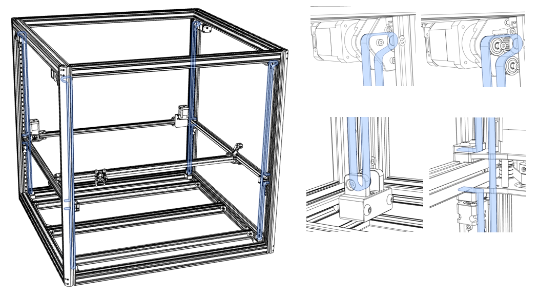
2.3.8 Z-axis Belt
- Pass the belt through the reduction motor and idler pulley as shown, and then fix it to the gantry assembly;
- Tighten all parts screws.
This chapter is assembled
Updated on: 01/07/2026
Thank you!