2.6 Drag chain components
2.6 Drag chain components
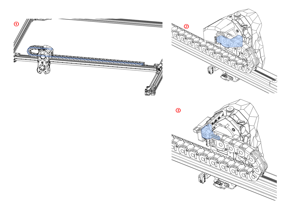
2.6.1 X-Drag Chain
- Assemble according to the diagram;
- Open the movable buckle on the back of the drag chain and insert the CAN line and the light bar power line;
- Use M3x8 BHCS screws to fix one end of the drag chain to the extruder head and the other end to the profile;
- CAN line plugged into the CAN board;The back of the XY drag chain is fixed with a drag chain buckle
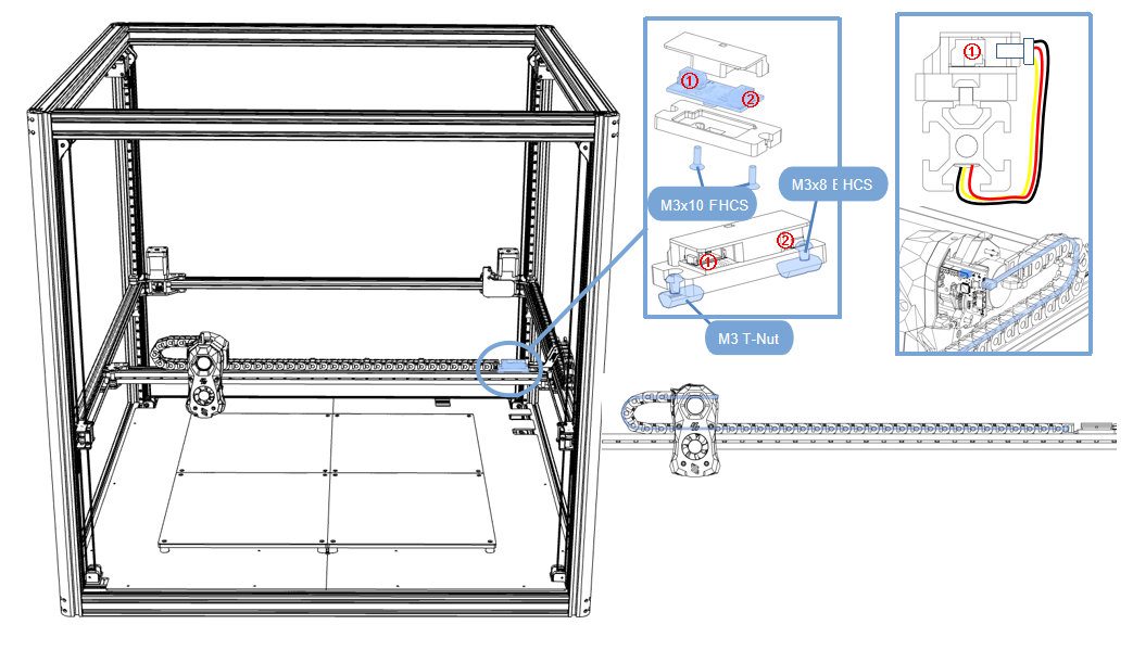
Gantry light bar power board
- The light bar cable is connected to port ①,See page 33;
- Port ② faces the drag chain and uses the power cable to connect to the CAN board;
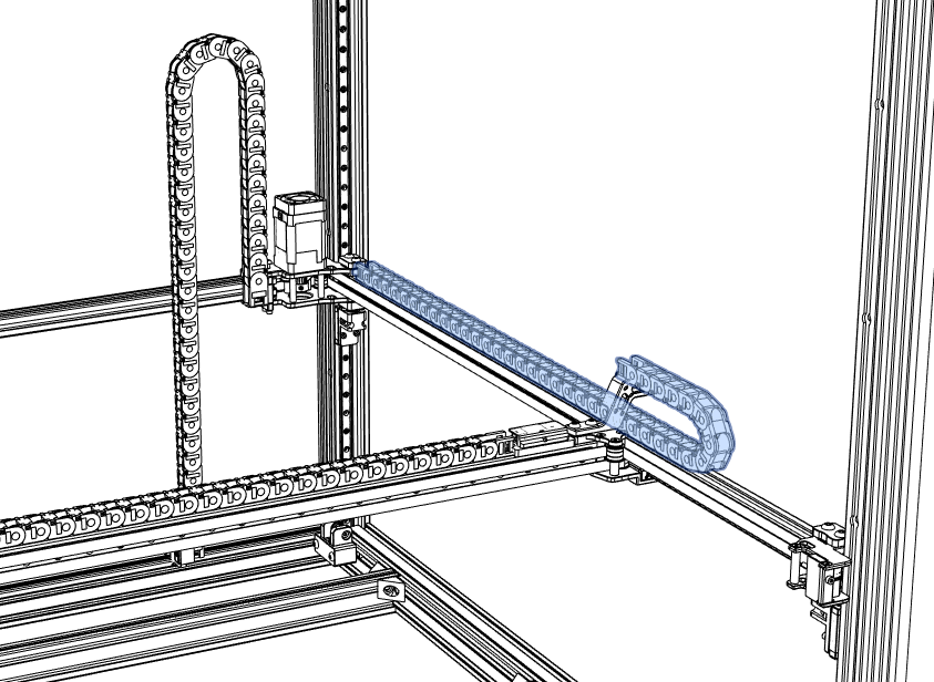
2.6.2 Y-Drag Chain
- Open the movable buckle on the back of the drag chain and insert the CAN line power line;
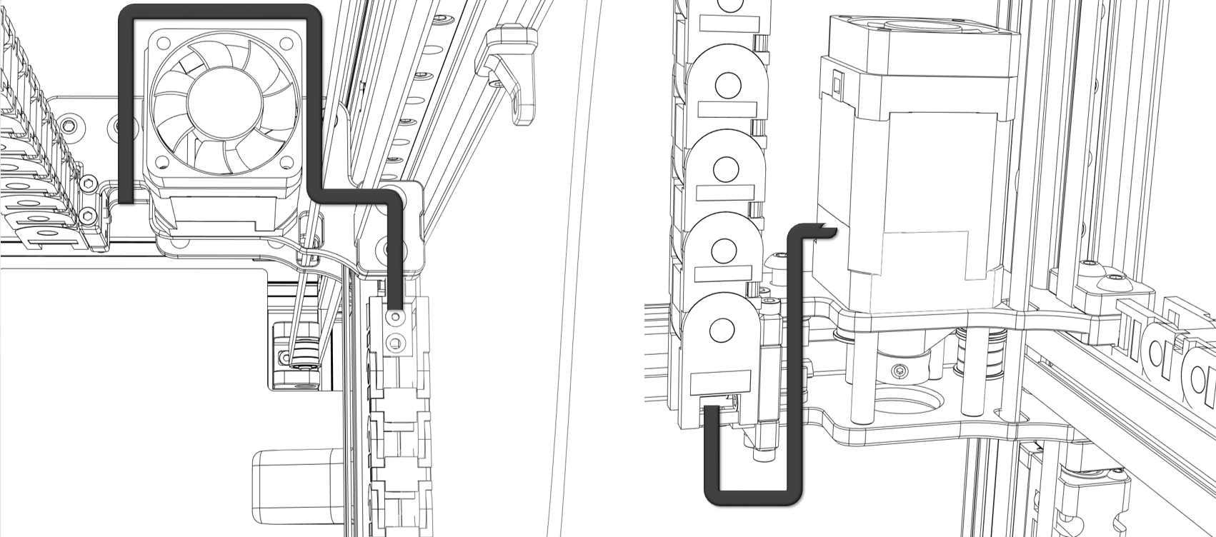
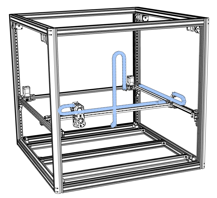
2.6.3 Z-Drag Chain
- Attach the cooling fan to the tail of the motor;
- Place the fan wire and motor wire B into the aluminum profile slot and cover them with the aluminum profile slot cover.
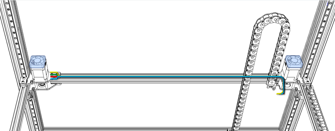
- Pass the AB motor wires and CAN board connection wires through the Z drag chain;
- Fix the drag chain with the drag chain fixings and tighten the screws;
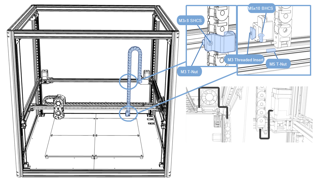
!!! abstract
NOTE: Note where the cables pass through.
!!!
This chapter is assembled
Updated on: 01/07/2026
Thank you!