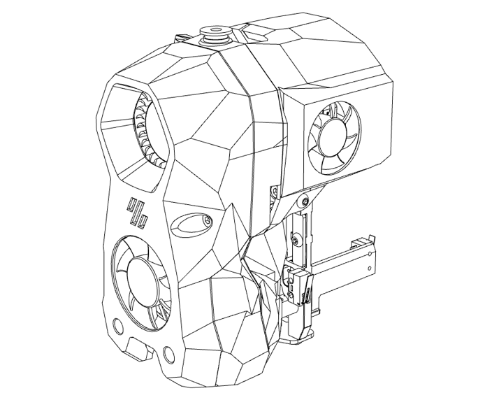
2.5 Extrusion head assembly
2.5 Extrusion head assembly
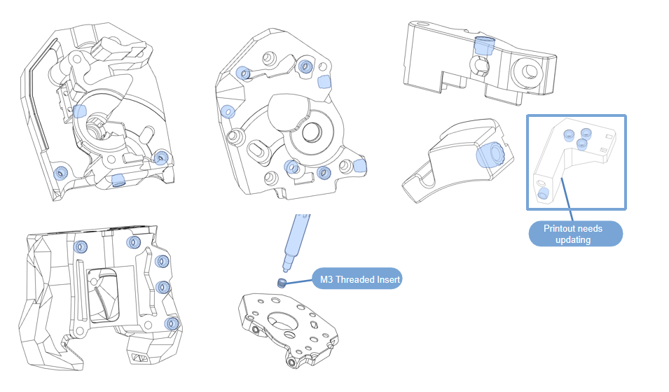
2.5.1 Printed hot melt nut
- Use a soldering iron to heat-weld the printed parts;
※Printout needs updating(Chain_Anchor_3_Hole_V2_Trident-G).https://github.com/FYSETC/Venture_XL/tree/main/STLs
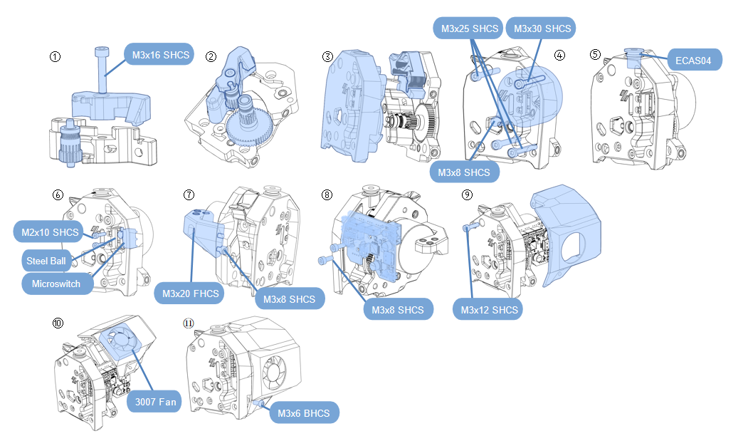
2.5.2 Extrusion Head Kit Assembly
- Assemble according to the diagram;
- Step ⑥ needs to flatten the pins of the micro switch;
- Step ⑧ needs to insert the motor terminal into the SB can board first;
- Complete the assembly together with the reference wiring diagram;
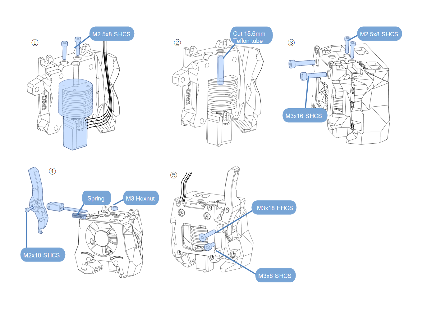
- Assemble according to the diagram;
- The blade in step ③ needs to be pressed in. The blade must be sharp and pay attention to safety.;
- Complete the assembly together with the reference wiring diagram;
!!! abstract
NOTE: Note where the cables pass through.
!!!
2.5.3 Extrusion Head Kit Installation
- Material preparation
- Assemble according to the diagram;
- Complete the assembly together with the reference wiring diagram
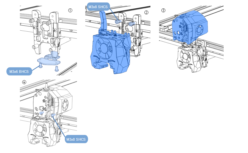
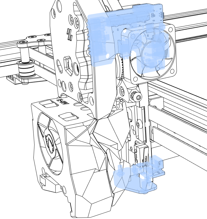
- Pay attention to the CAN installation position.
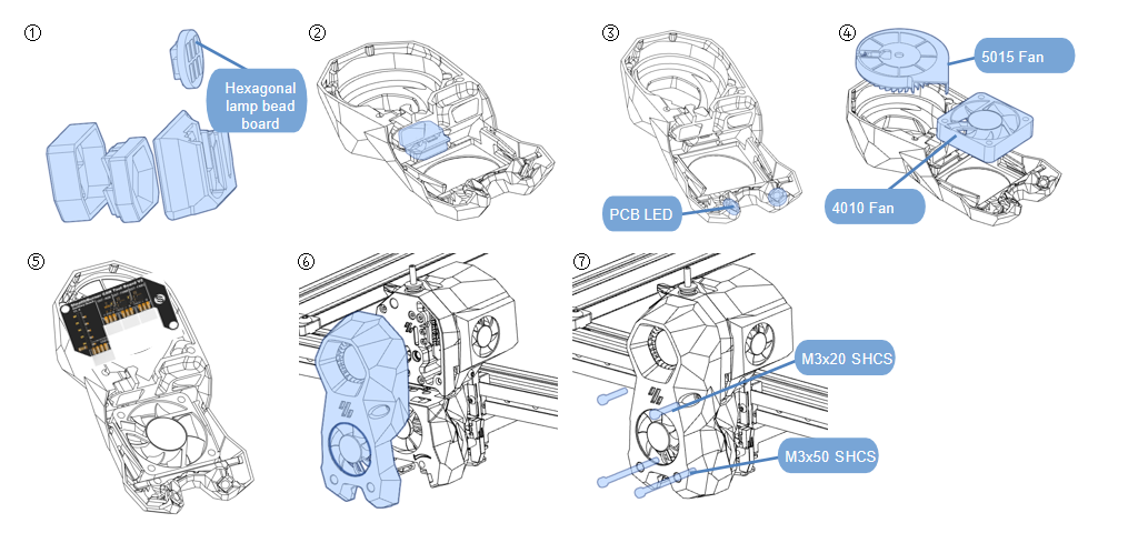
- Assemble according to the diagram;
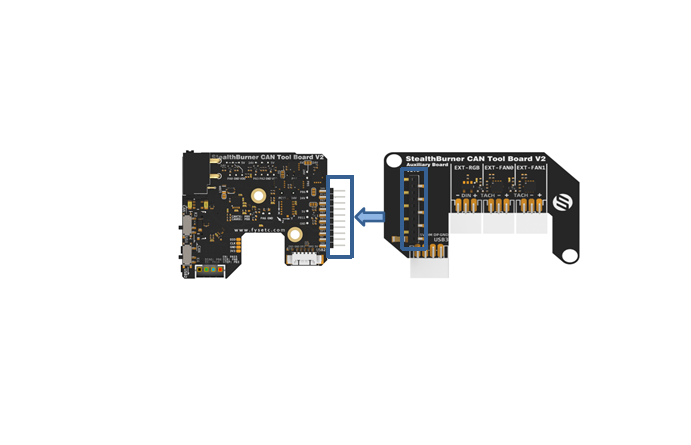
- Step ④: The CAB expansion board needs to be installed behind the 5015 Fan;
- Step ⑤: The CAN expansion board needs to be connected to the CAN board pins;
- Complete the assembly together with the reference wiring diagram;
!!! abstract
NOTE: Note where the cables pass through.
Wiring reference video link:https://www.youtube.com/watch?v=Fudc-D5RQZw
!!!
!!!
Refer to wiring.
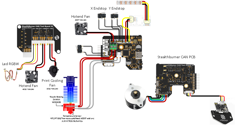
This chapter is assembled
Updated on: 01/07/2026
Thank you!