PSF Feedback Sensor
PSF Feedback Sensor
Product Introduction
During extended periods of synchronized printing without intervening tool changes, alignment between extruder and gear steppers can gradually drift. this mismatch accumulates and can lead to print artefacts caused by missed steps or suboptimal extrusion rates. Proportional sync-feedback sensors address this using linear Hall Effect sensors (or similar), providing real-time analog positional telemetry to Happy-Hare allowing it to continuously adjust and fine tune the following gear stepper's Rotational Distance (RD).

This is an improved version based on the design of Stumpy_PSF_Sensor
Official Link: https://github.com/ningpj/Stumpy_PSF_Sensor/tree/main
Compatible Printers
"Stumpy" PSF needs to be used in-conjunction with Happy-Hare Flowguard integrated support for Proportional Feedback Sensors (Release 3.4.2 or later). Please refer to https://github.com/moggieuk/Happy-Hare/wiki/Synchronized-Gear-Extruder2 for proportional sensor setup, configuration, and usage instructions.
BOM
Item | Specification | Quantity |
|---|---|---|
3D‑printed assembly kit | 3D‑printed assembly kit | 1 |
PSF Board | 1 | |
Spring | 0.4 mm × 6 mm × 25 mm | 1 |
Magnet | D4 mm × 15 mm | 1 |
cable | 1 | |
ECAS04 | 2 | |
Self‑tapping screw | M2×6 mm SHCS | 2 |
PTFE | 1 | |
Tool | 1.5mm | 1 |
connector housing | Use when the connecting cable is incompatible | 1 |
PSF Sensor Kit User Manual | 1 |
Assembly Steps
- Assembly of 3D‑printed parts‑ECAS04
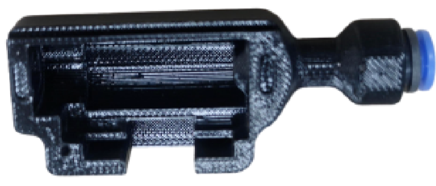
- Assemble 3D‑printed components with PCBs
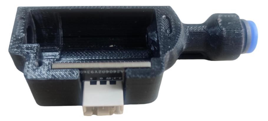
- Assemble 3D‑printed parts to ECAS04 as shown in the figure
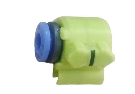
- Assemble the magnet. Its mounting direction is not important, and parameters can be tuned by software
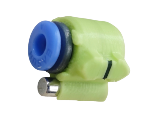
- Assemble 3D‑printed parts as shown in the figure.
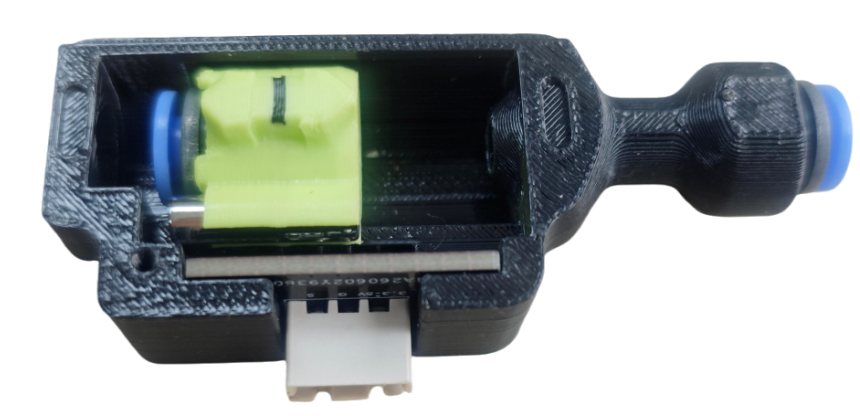
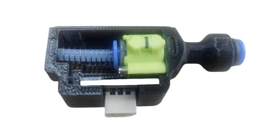
- Fit the spring and PTFE tube. Route the PTFE tube through the spring and connect to ECAS04.
- Fit on the cover plate, then tighten M2×6 screws.
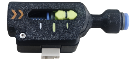
- Confirm the shuttle moves freely across its full travel before installing.
- Wiring.
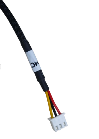
9.1. The connecting cable with a white "PSF" marking is connected to the PSF Feedback Sensor.
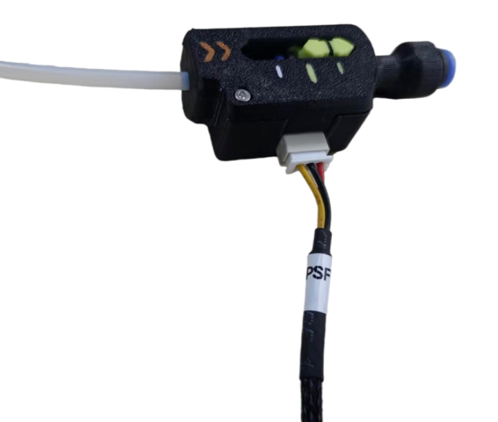
9.2. The other end connects to your FDM 3D‑printer main board. The yellow wire is the signal line; the red wire is the power supply line (3.3 V or 5 V is acceptable); the black wire is the ground wire.
Usage Steps
Happy Hare Installation
After logging into your Raspberry Pi using SSH, use the following commands to install Happy Hare.
cd ~
git clone https://github.com/moggieuk/Happy-Hare.git
cd ~/Happy-Hare
./install.sh -i
For more information, please refer to https://github.com/moggieuk/Happy-Hare/wiki/Installation
Happy-Hare Configuration
Modify the buffer range in the MMU_PARAMETERS.CFG file.
sync_feedback_buffer_range: 14.5 	# Travel in "buffer" between compression/tension or one sensor and end (see above)
sync_feedback_buffer_maxrange: 14.5 	# Absolute maximum end-to-end travel (mm) provided by buffer (see above)
ensure the following parameters are included
sync_to_extruder: 1
sync_feedback_enabled: 1
In MMU_HARDWARE.CFG set sync_feedback_analog_pin: mmu: to a valid analog-capable GPIO port on the MCU you connected the "Stumpy" PSF sensor to. If sync_feedback_* parameters aren't defined under your [mmu_sensor] section, insert the following block manually, setting compression, tension, and neutral_point to 1, 0, & 0.5 respectively.
sync_feedback_analog_pin: mmu:<Your analog-capable GPIO> # The ADC pin where the proportional filament pressure sensor is installed
sync_feedback_analog_max_compression: 0.9964             # Raw sensor reading at max filament compression (buffer squeezed)
sync_feedback_analog_max_tension: 0.0046                 # Raw sensor reading at max filament tension (buffer expanded)
sync_feedback_analog_neutral_point: 0.5005               # Sensor neutral point (tunable to apply positive tension on the filament to unburden the Bowden and extruder)
For Happy Hare, the CHAMELEON_X5 control board is recommended; for more details, please refer to https://github.com/FYSETC/CHAMELEON_X5.
Calibration
Happy-Hare provides a calibration command, MMU_CALIBRATE_PSENSOR, to automatically calibrate the values of the three ADCs.Before running this command, you need to load the filament into the toolhead.
$ MMU_CALIBRATE_PSENSOR
...
// Calibration Results:
// As wired the recommended setting (in mmu_hardware.cfg) is:
// [mmu_sensors]
// sync_feedback_analog_max_compression: 0.0023
// sync_feedback_analog_max_tension:     0.9979
// sync_feedback_analog_neutral_point:   0.5001
// After updating, restart klipper
...
Happy-Hare provides a command, MMU_QUERY_PSENSOR, to obtain the current raw ADC value. This can be used to determine if the wiring is correct.
$ MMU_QUERY_PSENSOR
echo: PSENSOR Enabled: True  Value: -1.0  Raw Value: 0.997
Assembly Video
You can watch the assembly video.
Video tutorial link: https://www.youtube.com/watch?v=cagph1cLVpE
You can also scan the QR code to view.

Attention
Please pay attention to the sensor's terminal wiring definitions; do not reverse the VCC and GND connections on the control board.
FAQ
- Q: How to verify correct sensor wiring?
A: MMU_QUERY_PSENSOR, to obtain the current raw ADC value.
Attachments
Shop
Tech Support
Disord Server: https://discord.gg/RXuwedUkB9
Facebook Group:https://www.facebook.com/groups/197476557529090/
Tech Support Email: support@fysetc.com
Updated on: 07/09/2026
Thank you!