CHAMELEON X5
Introduction
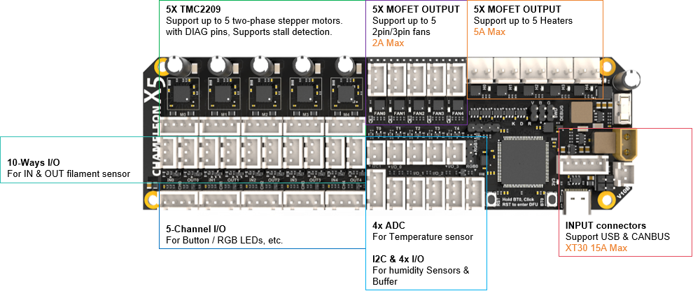
The Chameleon X5 can be used in various multi-color applications requiring multiple motors to work together, such as Type-A, Type-B, and Type-C systems. It also includes the necessary fan/heating control and temperature detection circuits for heating and drying functions.
It is based on the STM32F407VET6 microcontroller and TMC2209 stepper motor driver chip, with each channel equipped with the necessary I/O interfaces for filament input/output monitoring and status indication (buttons and LEDs) to ensure stable feeding.
The optional 5-channel heating and drying function includes dedicated interfaces for fan control and heating elements, as well as NTC temperature measurement, and also supports I2C sensors, such as temperature and humidity sensors.
Features
- Dimensions: 154mm x 48mm
- Based on STM32F407VET6 (168MHz Cortex-M4)
- Supports CANBUS & USB communication
- Onboard Power Supply:
- Input: 24V @ 15A max
- Onboard DC-DC power supply: 12V @ 3A, 5V @ 3A, 3.3V @ 0.8A
- 5-channel Material Feeding Support:
- 5 onboard TMC2209 drivers, supporting 5 stepper motors
- 10 general-purpose I/O pins for material insertion/extrusion monitoring
- 5 dual I/O connectors for buttons and LED indicators (with level shifting)
- 5-channel Hot Air Drying Support:
- 5x fans, support 2/3 fans, 12V/24V selectable, 2A Max
- 5x heating interfaces, 5A Max
- 5x NTC temperature sensor interfaces for temperature detection
- 1x I2C interface for temperature and humidity sensors
- 4x general-purpose I/O pins, use for external buffers
- 2x Neopixel RGB interfaces for indication or lighting
- Onboard BOOT0 and RST buttons
- Independent input interface board
Wiring
Powering The X5
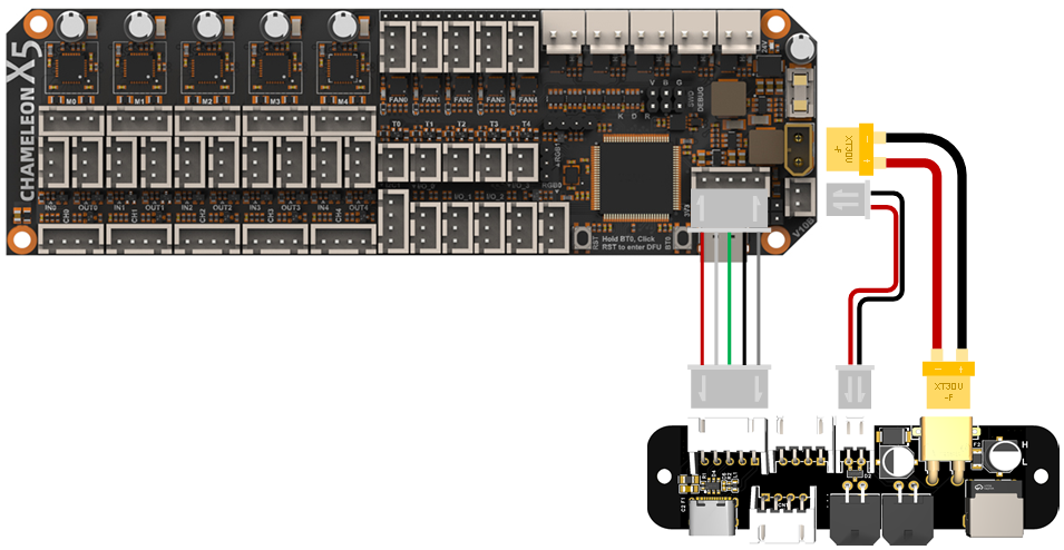
The X5 board needs an input voltage of 24v for both CAN and USB connection methods. This can be supplied via either the DC Barrel Jack or Microfit3 connector on the X5 I/O board.
DC Barrel Jack
The DC barrel jack is 5.5*2.1, and center-positive. This should be wired directly to 24v PSU of the printer.
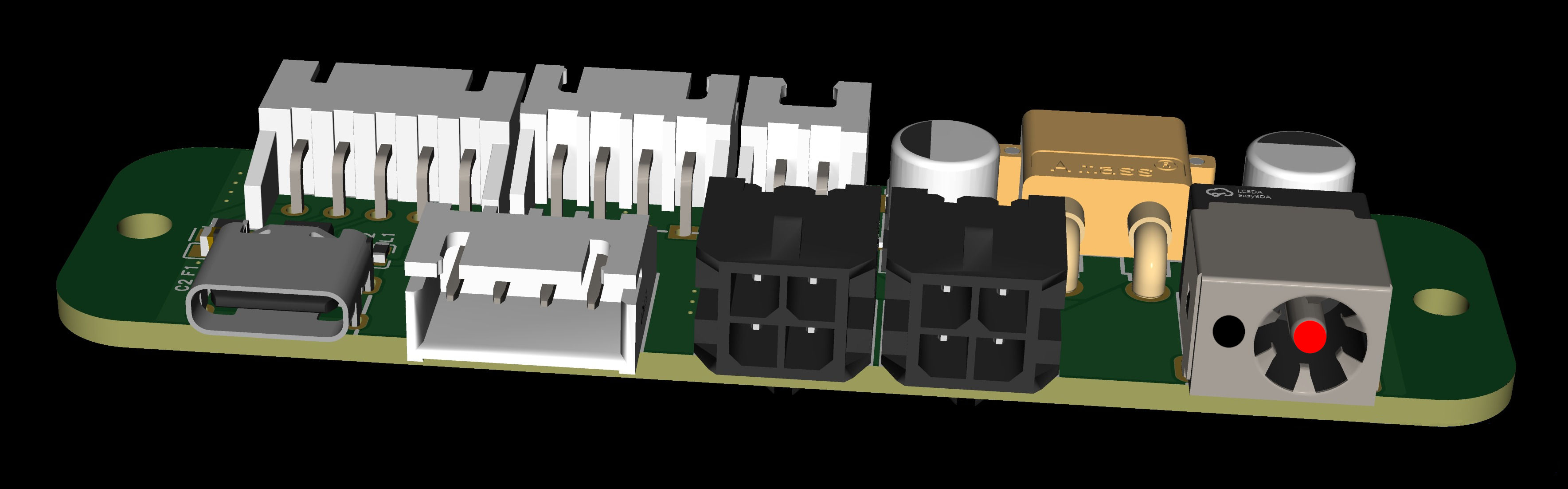
Barrel Jack | Value |
|---|---|
RED | 24v |
BLACK | GND |
MicroFit3
The microfit3 is a 2x2 female connector. This connector allows both the 24v and GND connections, as well as the CAN data connections.
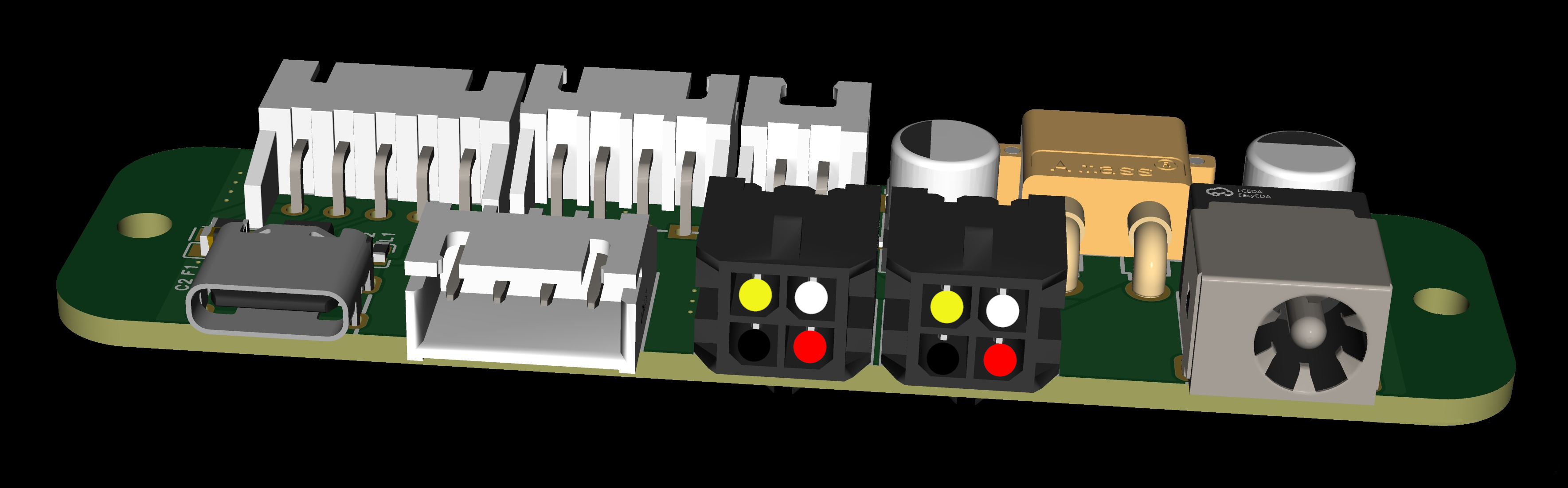
Microfit3 | Value |
|---|---|
RED | 24v |
BLACK | GND |
YELLOW | CAN H |
WHITE | CAN L |
USB
To use the Chameleon X5 on a USB connection, power the board with either the DC barrel jack or microfit3 connector and then connect the USB C cable from I/O board to the SBC (Raspberry Pi, Orange Pi, BTT Pi etc) of your printer.
CAN
To use the Chameleon X5 on a CAN connection. Use the microfit3 connector to supply both power and data using the diagram above to connect CAN H and CAN L to the corresponding CAN connection on your printer setup.
Wiring Examples
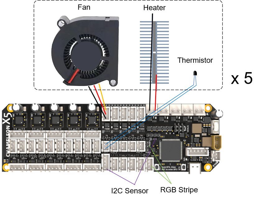
5 ways Heating and Drying example
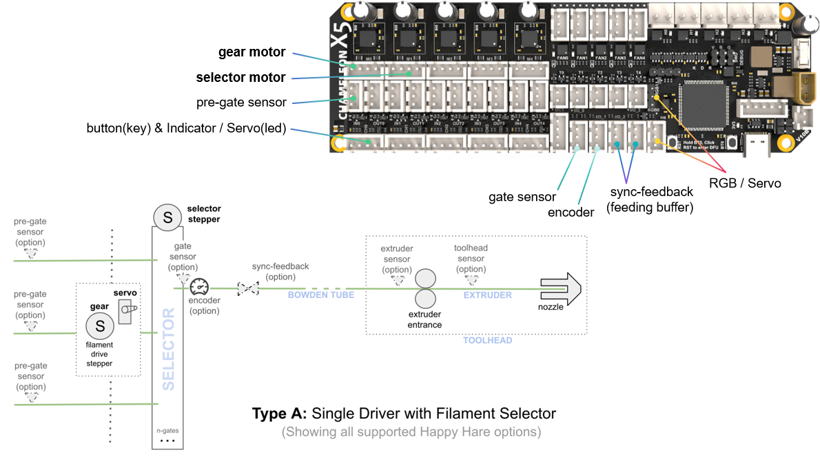
Type A usage example
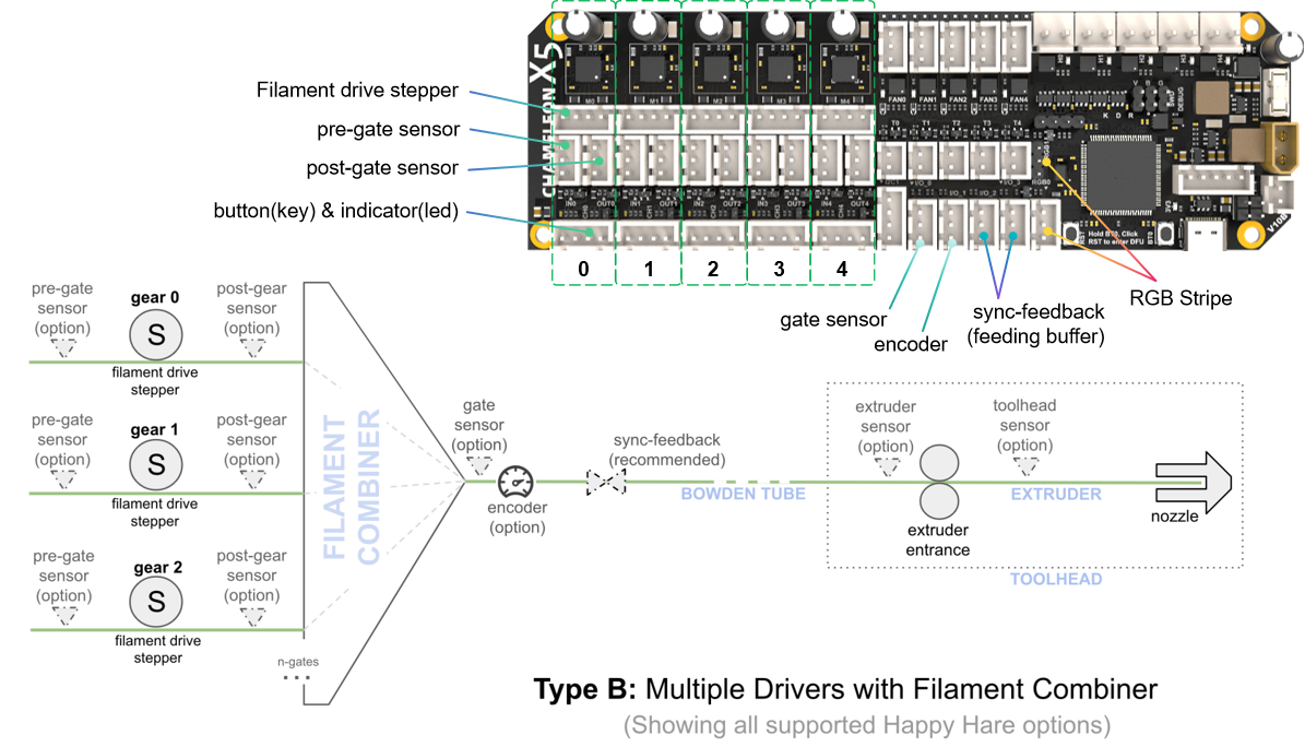
Type B usage example
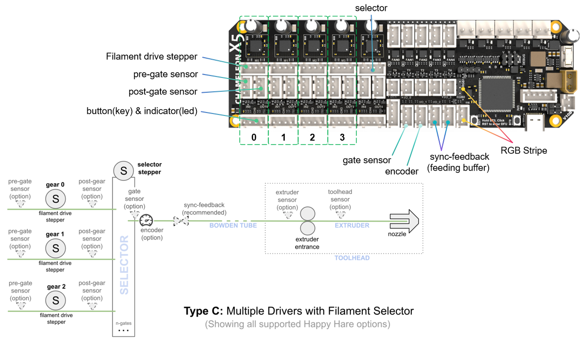
Type C usage example
X5 I/O Board
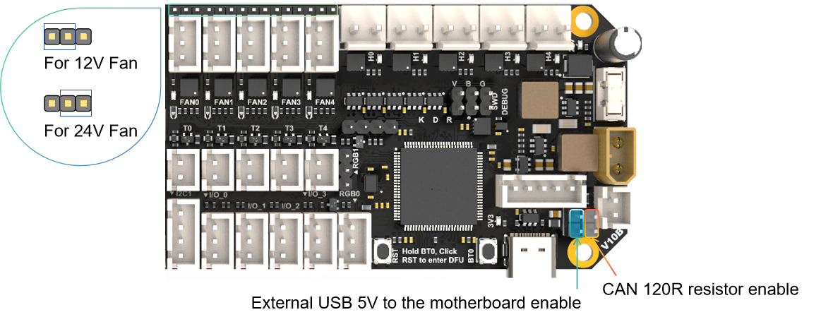
Jumpers
Firmware Guide
Firmware Configuration and Compilation
Using no bootloader
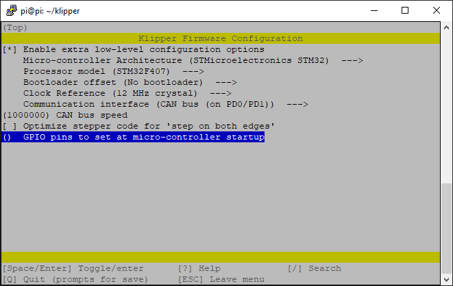
CANBUS communication mode
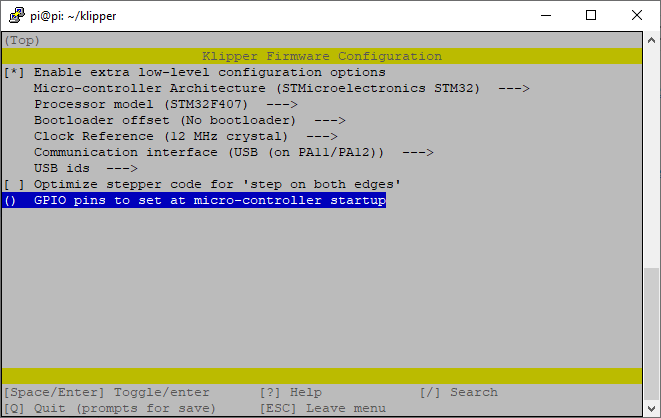
USB communication mode
Firmware Upload
DFU Mode
Firmware flashing can only be performed after entering DFU mode.
How to get in DFU mode:
- hold BT0 button for 2 seconds
- Hold RST button for 2 seconds
- Release the RST button
- wait 2seconds
- Release the BT0 button
"lsusb" check if get in DFU mode
No Bootloader Mode Upload
Command:
cd ~/klipper
make flash FLASH_DEVICE=0483:df11
Attachments
For more documents including configuration information, please check https://github.com/FYSETC/CHAMELEON\_X5
Support
Shop
Updated on: 03/08/2026
Thank you!