Spider V3.0 H7
1. Introduction
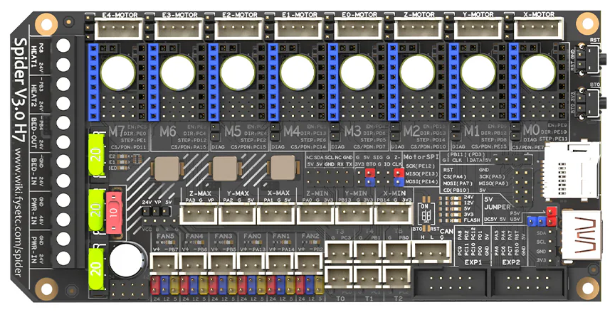
Spider V3.0 H7
The Fysetc Spider V3.0 H7 is a high-end 3D printer controller board aimed primarily at custom printers such as Voron builds, CoreXY machines, and heavily modified printers running Klipper. It's essentially an upgraded version of the earlier Spider V3.0 F446, with a much faster MCU and improved high-voltage motor support.
Features vs F446 version
- STM32H723VGT6 @ 550Mhz
- Independent Motor Power input, 60V Peak (removed one MOSFET ouptut)
- Voltage Selector on every Driver
- 120uF/63V Capacitor for Motor Driver
- DotStar RGB Support
2. Features
Feature | Spider V3.0 H7 |
|---|---|
MCU | STM32H723VGT6 |
CPU Speed | 550 MHz |
Stepper Driver Slots | 8 |
Firmware Support | Klipper, Marlin, RepRap Firmware |
USB | USB-C |
CAN Bus | Built-in transceiver |
Motor Voltage | Selectable 24V / 48V |
Peak Motor Input | Up to 60V |
RGB Support | DotStar LEDs |
Form Factor | Same general layout as earlier Spider boards |
2.1 Whats Included
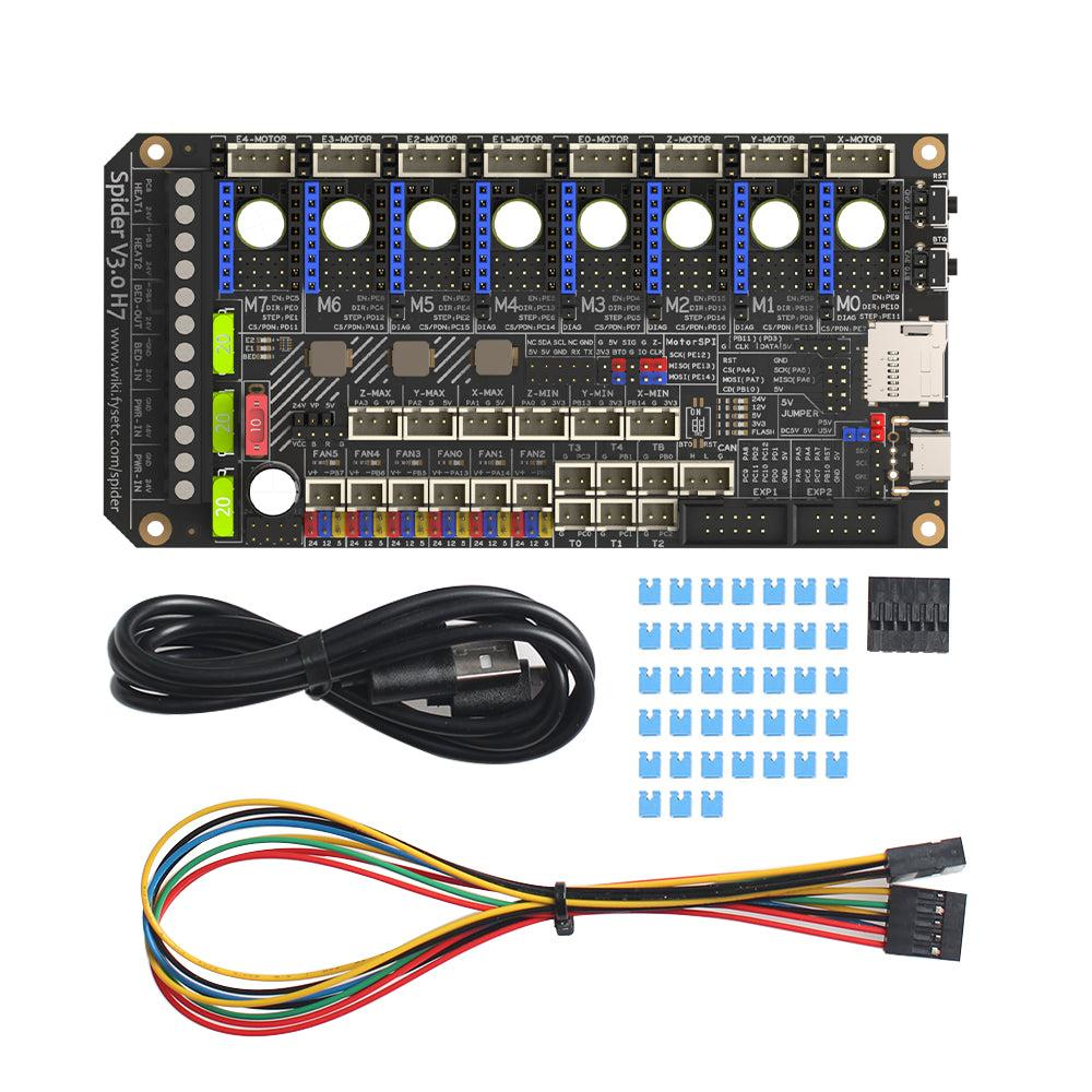
- FYSETC Spider V3 H7 Board
- 2 x 5 Double DuPont Cable
- 30 x Jumper Caps
- USB Type C - USB A Cable
3. Hardware Guide
3.1 GPIO and Pin Assignments
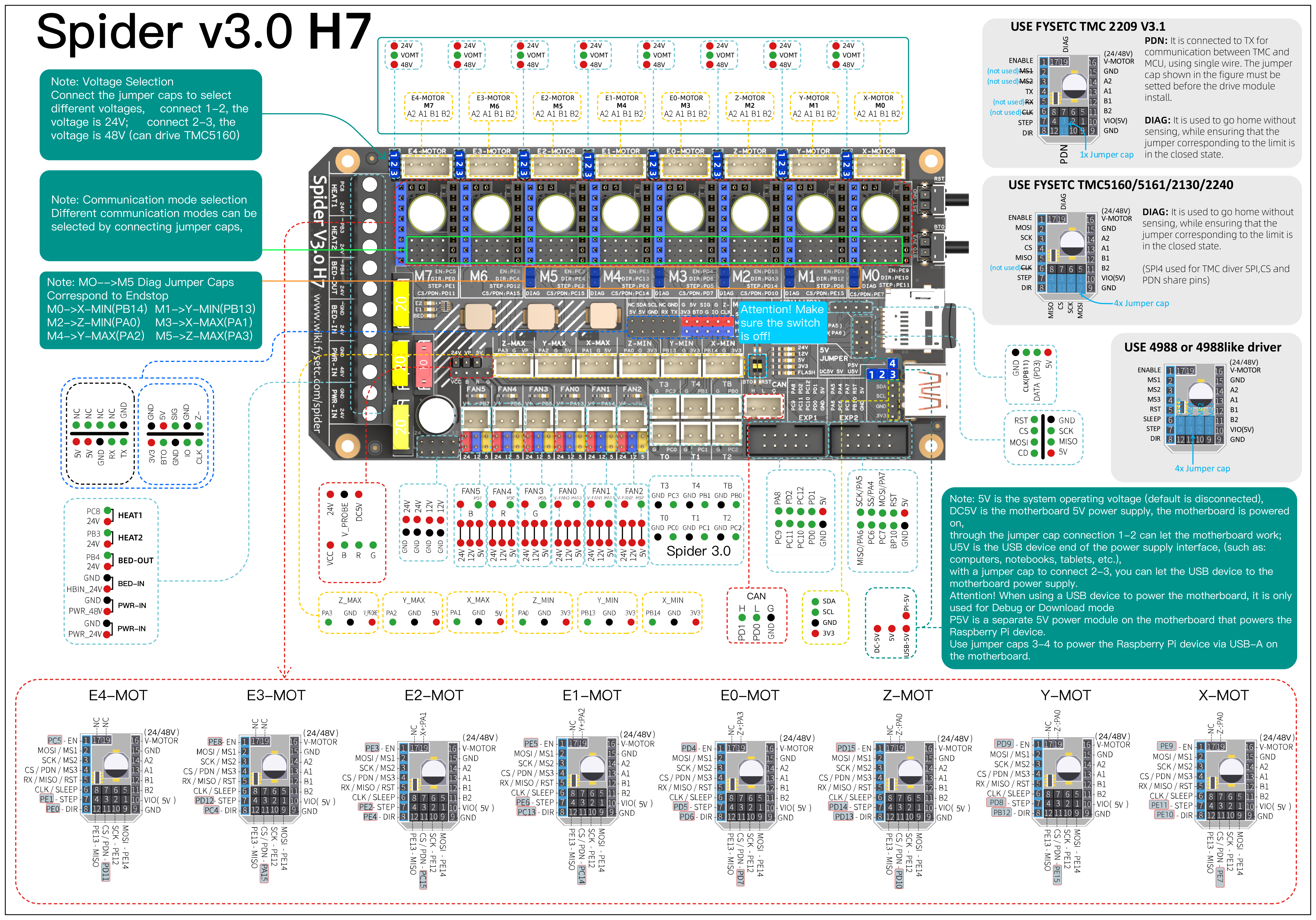
3.2 Pin Definition
3.2.1 Spider v3.x H7
Features | Spider Pin | STM32 Pin | Pin No. | Comment |
|---|---|---|---|---|
X-MOTOR(1) | X-Step | PE11 | 42 | |
X-MOTOR(1) | X-DIR | PE10 | 41 | |
X-MOTOR(1) | X-EN | PE9 | 40 | |
X-MOTOR(1) | X-CS/PDN | PE7 | 38 | |
Y-MOTOR(2) | Y-Step | PD8 | 55 | |
Y-MOTOR(2) | Y-DIR | PB12 | 51 | |
Y-MOTOR(2) | Y-EN | PD9 | 56 | |
Y-MOTOR(2) | Y-CS/PDN | PE15 | 46 | |
Z-MOTOR(3) | Z-Step | PD14 | 61 | |
Z-MOTOR(3) | Z-DIR | PD13 | 60 | |
Z-MOTOR(3) | Z-EN | PD15 | 62 | |
Z-MOTOR(3) | Z-CS/PDN | PD10 | 57 | |
E0-MOTOR(4) | E0-Step | PD5 | 86 | |
E0-MOTOR(4) | E0-DIR | PD6 | 87 | |
E0-MOTOR(4) | E0-EN | PD4 | 85 | |
E0-MOTOR(4) | E0-CS/PDN | PD7 | 88 | |
E1-MOTOR(5) | E1-Step | PE6 | 5 | |
E1-MOTOR(5) | E1-DIR | PC13 | 7 | |
E1-MOTOR(5) | E1-EN | PE5 | 4 | |
E1-MOTOR(5) | E1-CS/PDN | PC14 | 8 | |
E2-MOTOR(6) | E2-Step | PE2 | 1 | |
E2-MOTOR(6) | E2-DIR | PE4 | 3 | |
E2-MOTOR(6) | E2-EN | PE3 | 2 | |
E2-MOTOR(6) | E2-CS/PDN | PC15 | 9 | |
E3-MOTOR(7) | E3-Step | PD12 | 39 | |
E3-MOTOR(7) | E3-DIR | PC4 | 33 | |
E3-MOTOR(7) | E3-EN | PE8 | 59 | |
E3-MOTOR(7) | E3-CS/PDN | PA15 | 77 | |
E4-MOTOR ( 8 ) | E4-Step | PE1 | 34 | |
E4-MOTOR ( 8 ) | E4-DIR | PE0 | 97 | |
E4-MOTOR ( 8 ) | E4-EN | PC5 | 98 | |
E4-MOTOR ( 8 ) | E4-CS/PDN | PD11 | 58 | |
TMC Driver SPI (SPI4) | MOSI | PE14 | 45 | |
TMC Driver SPI (SPI4) | MISO | PE13 | 44 | |
TMC Driver SPI (SPI4) | SCK | PE12 | 43 | |
End-stops | X-MIN | PB14 | 53 | Share with X-DIAG |
End-stops | X-MAX | PA1 | 24 | Share with E0-DIAG |
End-stops | Y-MIN | PB13 | 52 | Share with Y-DIAG |
End-stops | Y-MAX | PA2 | 25 | Share with E1-DIAG |
End-stops | Z-MIN | PA0 | 23 | Share with Z-DIAG |
End-stops | Z-MAX(Probe) | PA3 | 26 | Share with E2-DIAG |
FAN/RGB | FAN0 | PA13 | 72 | |
FAN/RGB | FAN1 | PA14 | 76 | |
FAN/RGB | FAN2 | PB2/BOOT1 | 37 | |
FAN/RGB | LED-R | PB6 | 92 | Can be used for fan3 |
FAN/RGB | LED-G | PB5 | 91 | Can be used for fan4 |
FAN/RGB | LED-B | PB7 | 93 | Can be used for fan5 |
FAN/RGB | 5V-LED(WS2812) | PD3 | 84 | Share with flash indicator(Bootloader) |
Heating | E0-Heater | PB15 | 54 | |
Heating | E1-Heater | PC8 | 65 | |
Heating | E2-Heater | PB3 | 89 | |
Heating | Heated-Bed | PB4 | 90 | |
Temperature | TE0(THERM0) | PC0 | 15 | A 4.7kOhm 0.1% temperature sensor pull up resistor is used,PT1000 can be connected directly. For PT100, an amplifier board must be used. |
Temperature | TE1(THERM1) | PC1 | 16 | A 4.7kOhm 0.1% temperature sensor pull up resistor is used,PT1000 can be connected directly. For PT100, an amplifier board must be used. |
Temperature | TE2(THERM2) | PC2 | 17 | A 4.7kOhm 0.1% temperature sensor pull up resistor is used,PT1000 can be connected directly. For PT100, an amplifier board must be used. |
Temperature | TE3(THERM3) | PC3 | 18 | A 4.7kOhm 0.1% temperature sensor pull up resistor is used,PT1000 can be connected directly. For PT100, an amplifier board must be used. |
Temperature | TE4(THERM4) | PB1 | 36 | A 4.7kOhm 0.1% temperature sensor pull up resistor is used,PT1000 can be connected directly. For PT100, an amplifier board must be used. |
Temperature | TB(THERM3) | PB0 | 35 | A 4.7kOhm 0.1% temperature sensor pull up resistor is used,PT1000 can be connected directly. For PT100, an amplifier board must be used. |
EXP2 | LCD_D7 | PD1/CAN-TX1 | 82 | Share with CAN-TX1 |
EXP2 | LCD_D6 | PD0/CAN-RX1 | 81 | Share with CAN-RX1 |
EXP2 | LCD_D5 | PC12/MOSI3/TX5/SDA2 | 80 | |
EXP2 | LCD_D4 | PC10/SCK3/TX3/4 | 78 | |
EXP2 | LCD_EN | PC11/MISO3/RX3/4 | 79 | |
EXP2 | LCD_RS | PD2/RX5 | 83 | |
EXP2 | ENC_C | PA8/SCL3 | 67 | |
EXP2 | BEEP | PC9/SDA3 | 66 | |
EXP1 | RESET | NRST | 14 | |
EXP1 | ENC_A | PC6/TX6 | 63 | |
EXP1 | ENC_B | PC7/RX6 | 64 | |
EXP1 | SD-DET | PB10/SCL2 | 47 | |
EXP1 | SD-MISO | PA6/MISO1 | 31 | |
EXP1 | SD-MOSI | PA7/MOSI1 | 32 | |
EXP1 | SCK | PA5/SCK1 | 30 | |
EXP1 | CS | PA4/CS1 | 29 | |
EEPROM(4K) I2C Pin-Out | SCL | PB8/SCL1 | 95 | Connect to 24LC32(4K EEPROM) |
EEPROM(4K) I2C Pin-Out | SDA | PB9/SDA1 | 96 | Connect to 24LC32(4K EEPROM) |
Pi_PWR/UART | TX | PA9/TX1 | 68 | |
Pi_PWR/UART | RX | PA10/RX1 | 69 | |
SWD Debug | PA13/SWDIO | 72 | only used for debugging now and can be used for other purposes. | |
SWD Debug | PA14/SWCLK | 76 | only used for debugging now and can be used for other purposes. |
3.3 Wiring
3.3.1 CAN
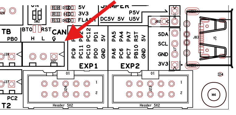
There is a permanent 120 ohm termination resistor soldered to the board, no need to add a jumper to enable it and also no ability to disable it.
The CAN port on the Spider V3.0 H7 is a 3 pin JST-XH header located here:
4. Firmware Guide
DFU mode
To put the Spider V3.0 H7 into DFU mode, hold the BT0 button and while still holding press and release the RST button. Then count to 5 and release the BT0 button.
4.1 Klipper
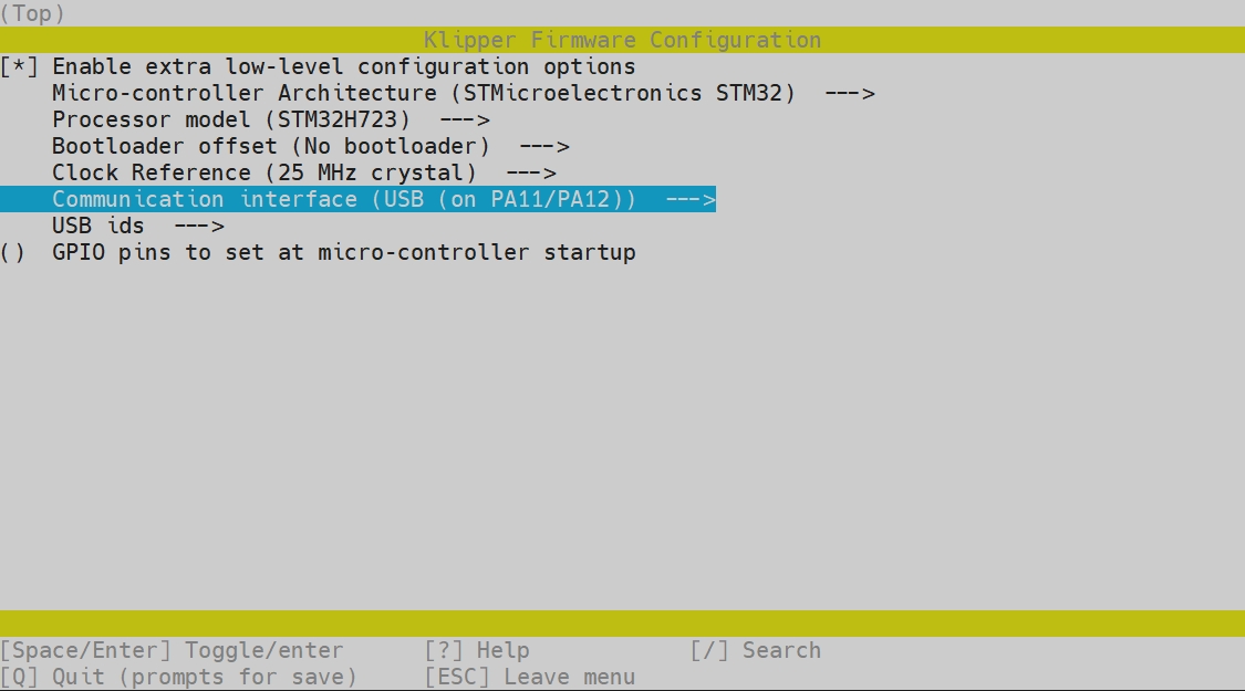
4.1.1 USB
- [*] Enable extra low-level configuration options
- Micro-controller Architecture (STMicroelectronics STM32)
- Processor model (STM32H723)
- Bootloader offset (No bootloader)
- Clock Reference (25 Mhz crystal)
- Communication interface (USB (on PA11/PA12))
- USB ids (leave default)
- () GPIO pins to set at micro-controller startup
4.1.2 CAN
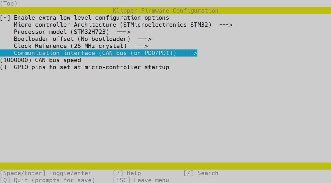
- [*] Enable extra low-level configuration options
- Micro-controller Architecture (STMicroelectronics STM32)
- Processor model (STM32H723)
- Bootloader offset (No bootloader)
- Clock Reference (25 Mhz crystal)
- Communication interface (CAN bus (on PD0/PD1))
- (1000000) CAN bus speed
- () GPIO pins to set at micro-controller startup
4.1.3 CAN Bridge
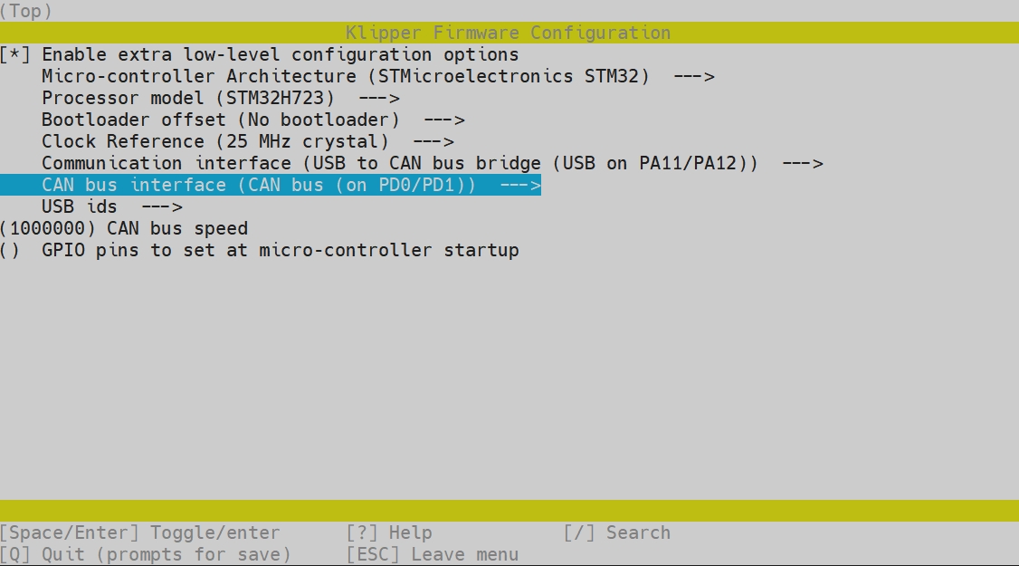
- [*] Enable extra low-level configuration options
- Micro-controller Architecture (STMicroelectronics STM32)
- Processor model (STM32H723)
- Bootloader offset (No bootloader)
- Clock Reference (25 Mhz crystal)
- Communication interface (USB to CAN bus bridge (USB on PA11/PA12))
- (1000000) CAN bus speed
- () GPIO pins to set at micro-controller startup
4.2 RRF
Please refer to the docs provided by TeamGloomy for RepRap Firmware on the Spider V3.0 H7.
https://teamgloomy.github.io/fysetc\_spider\_h723\_general\_3\_5.html
5. Where to buy
6. Tech Support
You can find extra resouces in our github https://github.com/FYSETC/FYSETC-SPIDER-H7 Or submit any technical issues into our Discord Server
7. Related Articles
Updated on: 03/08/2026
Thank you!