SPIDER
1. Product Introduction
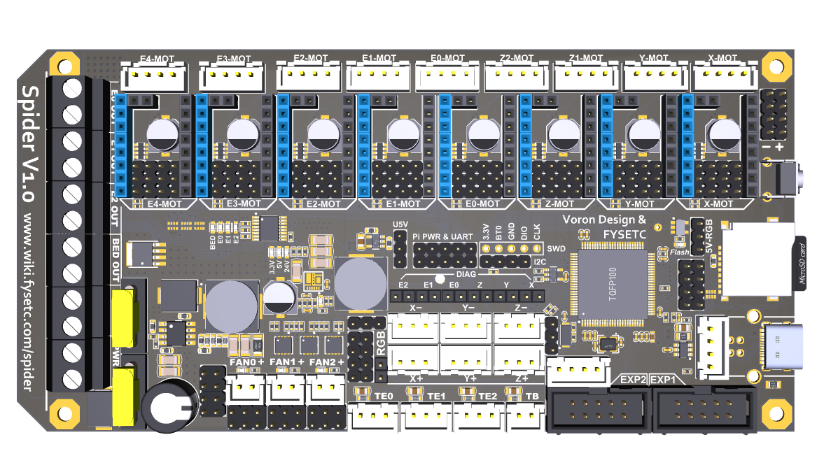
SPIDER is a small but powerful 3D printer control board. In a limited space, it integrates 8 stepper motor drives, 5A 12V power supply, 8A 5V power supply, which provides powerful energy for fans of various voltages, various RGB light strips and Raspberry Pi.
You can build a 3D printer with rich functions through SPIDER. Especially for VORON V2.4, we cooperated with the VORON team in the early stage of design, and many features have been recognized by the VORON team. If you are building VORON, this will be your best choice.
1.1 Change log
1.1.1 Spider v1.1
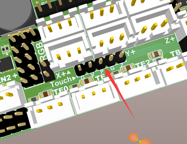
- Add 5pin connector for BL-Touch
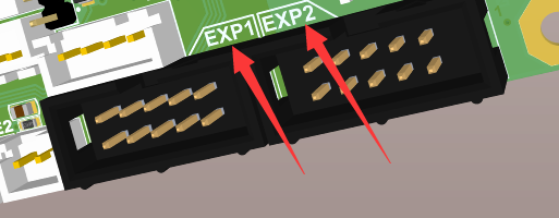
- Switch EXP1 & EXP2 mark(Only mark, not socket)
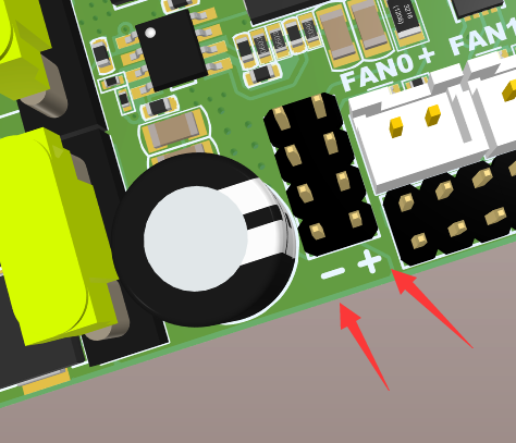
- Add +/- mark
- Add room for RaspberryPI USB-A power supply port
You can solder the below USB port, then you can power-up RPI with a USB-A cable. It is USB power-supply port without USB signal.

1.1.2 Spider v2.x
V2.0
- Add 48V stepstick support x3
- Add TVS and Bleeding resistance to every stepstick socket
- Change 12V/5A to SY8205
- Change the Raspberry Pi 5V and system 5V to separate DC-DC circuits (3A per channel)
- Add separate 3.3V to stepsticks
- Change PCB to 6 layers
- Optimize some wiring.
- Change the series diode of the driver circuit to a 15A fuse(1808)
V2.1
- Change 48V stepstick support to 2
- Change 12V/5A to 12V/3A
- Change the Raspberry Pi 5V (3A to 5A) and system 5V(5A to 3A )
- Add RESET 1x2 Pin header
V2.2
- Add two thermistor sockets, a total of 6.
- Change FAN0 to PA13,FAN1 to PA14
- Add pin definition silkscreen on the bottom.
V2.3
- Change 12v-24v RGB port layout to 3 fan ports, which can be used as a fan port more conveniently and still maintain RGB output support
- Optimize the fan control circuit, upgrade the buffer chip to independent triode control, enhance stability and greatly improve safety performance
- All motor drive module interface communication networks add high voltage buffering and voltage clamping processing, adding a shield to the MCU
- Re-layout the PCB, connectors position changed
1.1.3 Spider v3.x
V3.0
- Added 74HCT365 buffers for all stepper motor drive signals. All the motor drive IO signal voltages are changed from 3.3V to 5V, the driving ability is enhanced, and the external driver connettion is simpler.
- An onboard CAN transceiver is added to enable the mainboard to communicate directly with CAN devices, no need for expansion boards.
- A 3.3V power supply indicator is added, and different power supplies are indicated by LEDs of different colors, so that the working status of each power supply on the motherboard can be seen at a glance.
- The main board has been re-layouted, and all the marks are placed on the top layer, which makes it easier for users to view the marks of the pins and easier for firmware configuration.
- Connect the BOOT0 and RESET pins of the STM32 to the Pi's IO through the switch (disconnected by default), which provides the basis for directly entering the programming mode through the Pi.
2. Features
- Compact size: 155.3mm x 76.5mm
- Based on STM32F446 180Mhz,all IOs can withstand 5V voltage
- 8 TMC stepper drivers support, with Uart&SPI support
- V2.2:Add Two 60V-Max stepper driver slot
- Improved TMC jumper settings again,simpler and easier
- V1.0&V1.1: 28V input max,12V@5A DC-DC,**5V@8A DC-DC (Especially for Raspberry Pi)**,3.3V@0.8A LDO
- V2.2: 28V input max,12V@3A DC-DC,5V@5A DC-DC for Raspberry,5V@3A DC-DC for mcu and RGB, Two 3.3V@0.8A LDO for MCU and motors
- Two car fuses for hot bed input and main power input
- Limit switch socket 24V/5V/3.3V optional, ready for more other equipment, such as -inductive sensor, BL-Touch
- XH2.54 connectors
- 10x PWM capable power mosfet outputs (1 for HotBed, 3 for Heat-End, 3 for fans, 3 for RGB LED strip)
- V1.0&V1.1: 3pin temperature header, you can use thermistor or thermocouple (requires AD597 module)
- V2.2: Up to 6 temperature sensors support
- Up to 8 ways PWM fans (only use 1 extrueder and no 12V/24V RGB used ),2 ways RGB led(12V & 24V optional) ,1 way 5V-RGB led (NEO-PIXEL/WS2812)
- RepRapDiscount SmartController compatible pin header on board
- UART1-Raspberry Pi pin header (including 5V@8A power supply)
- 2X4 PinHeader Out for SD Card moudle
- Onboard micro-SD card
- Type-C and Type-B USB connector optional
- EXP1 & EXP2 have more multiplexing functions, such as USART, I2C, CAN
- SD card & USB upload support
- A 4.7kOhm 0.1% temperature sensor pull up resistor is used, PT1000 can be connected directly. For PT100, an amplifier board must be used.
- V2.2: Add more protection (TVS for each motor divers, current limit resistor, VMOT fuse)
3. Hardware Guide
3.1 Spider wiring
3.1.1 Spider v1.0 wiring
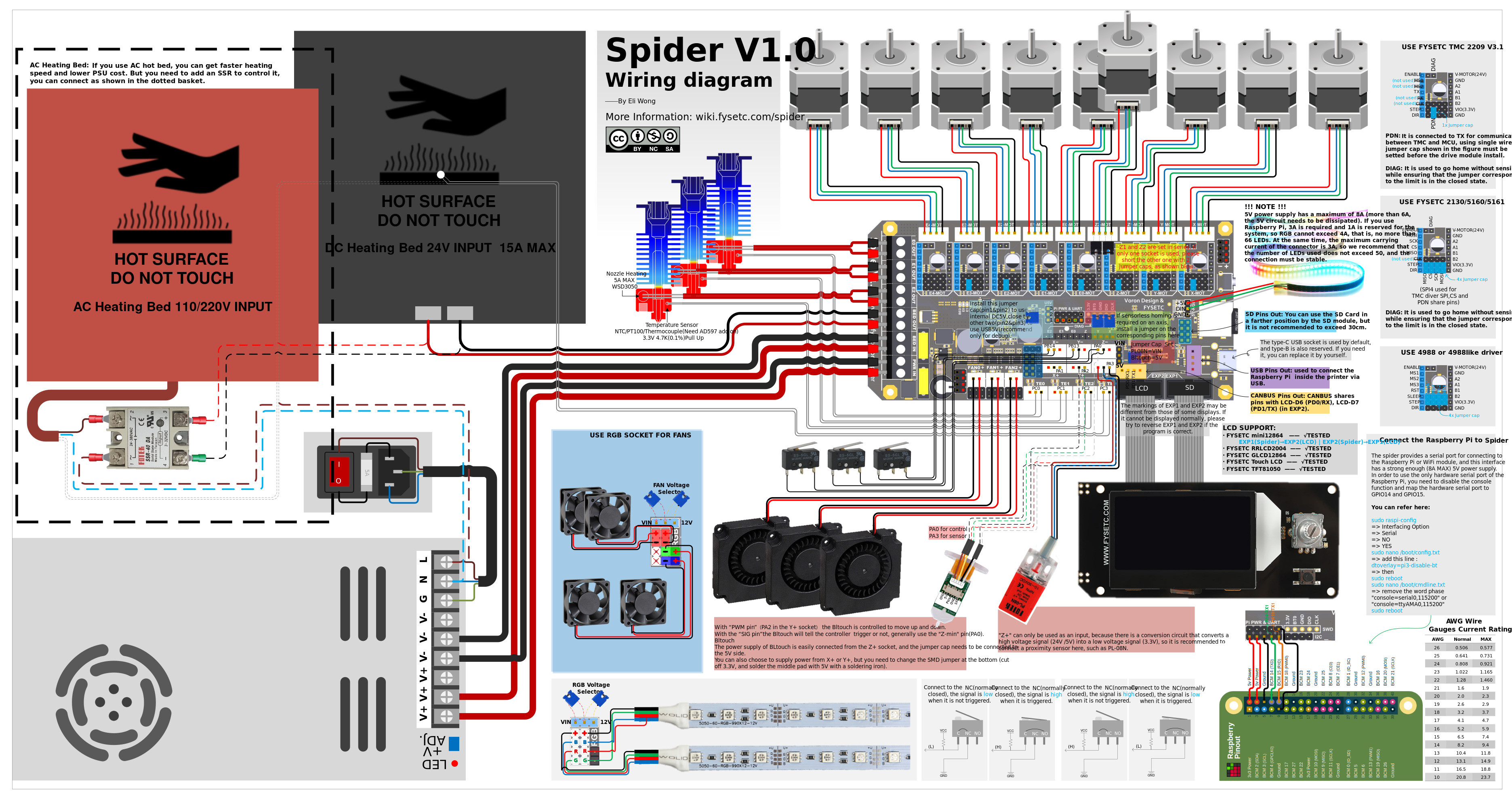
3.1.2 Spider v1.1 wiring

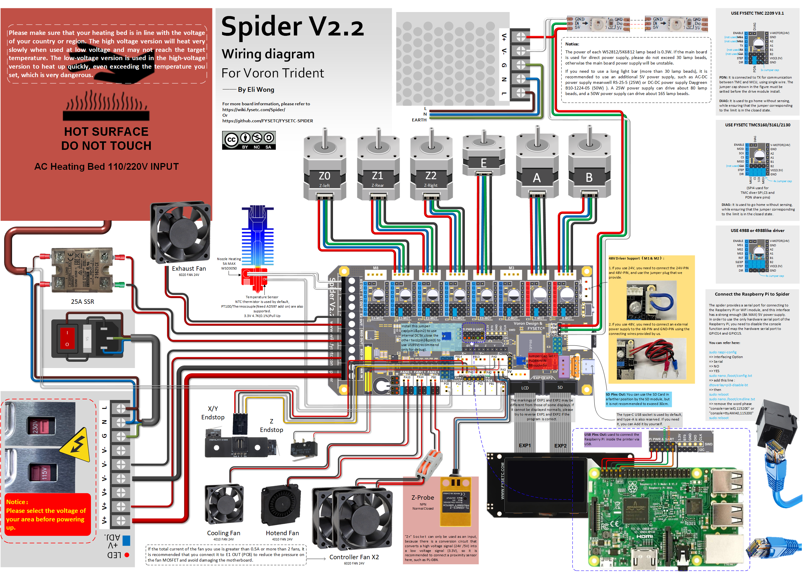
3.1.3 Spider v2.2 wiring

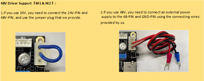
48v and 24v connector
Spider v2.2 wiring for VORON 2.4

Spider v2.2 wiring for VORON Trident
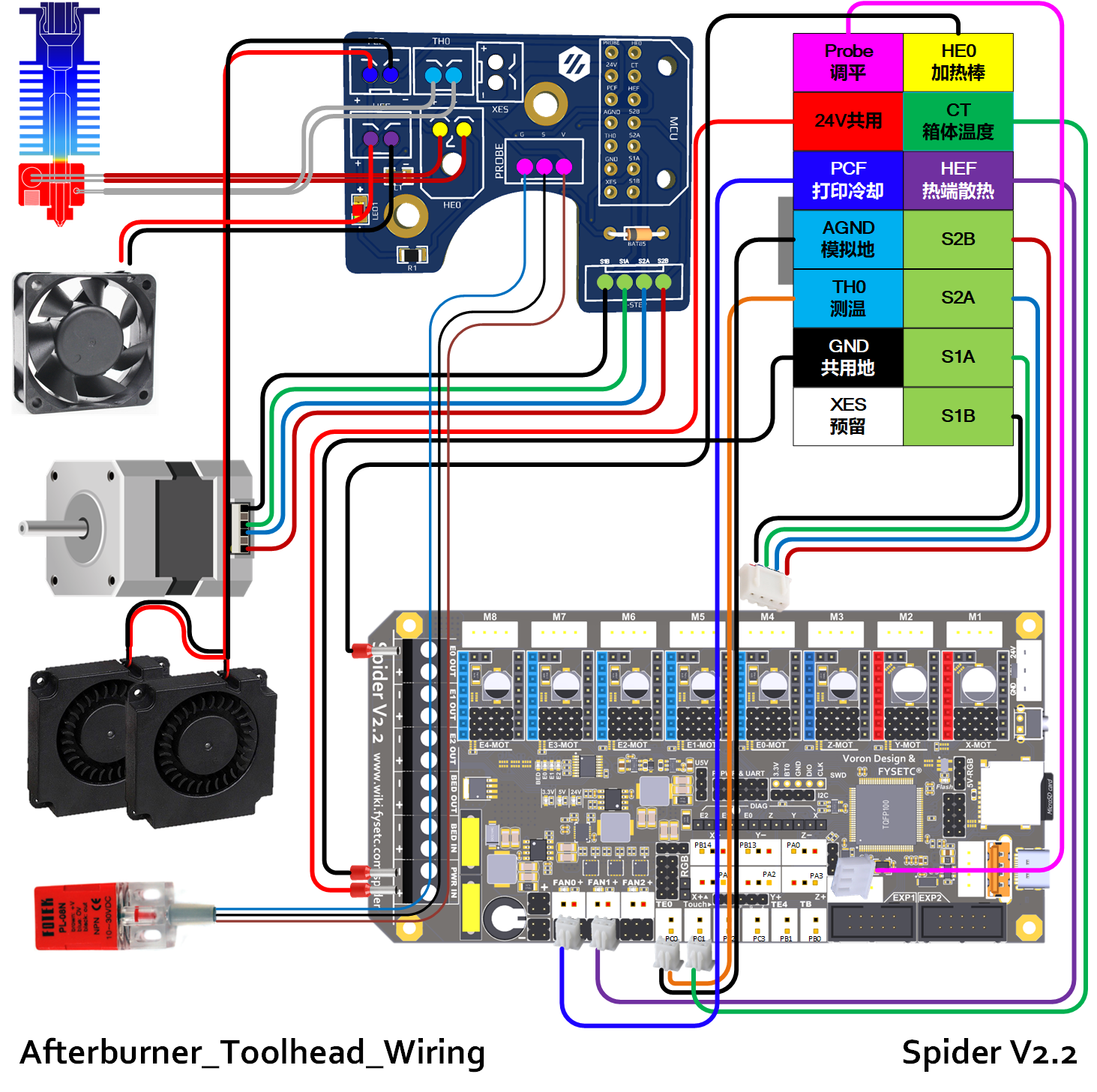
Spider v2.2 Afterburner Toolhead wiring
3.1.4 Spider v2.3 wiring
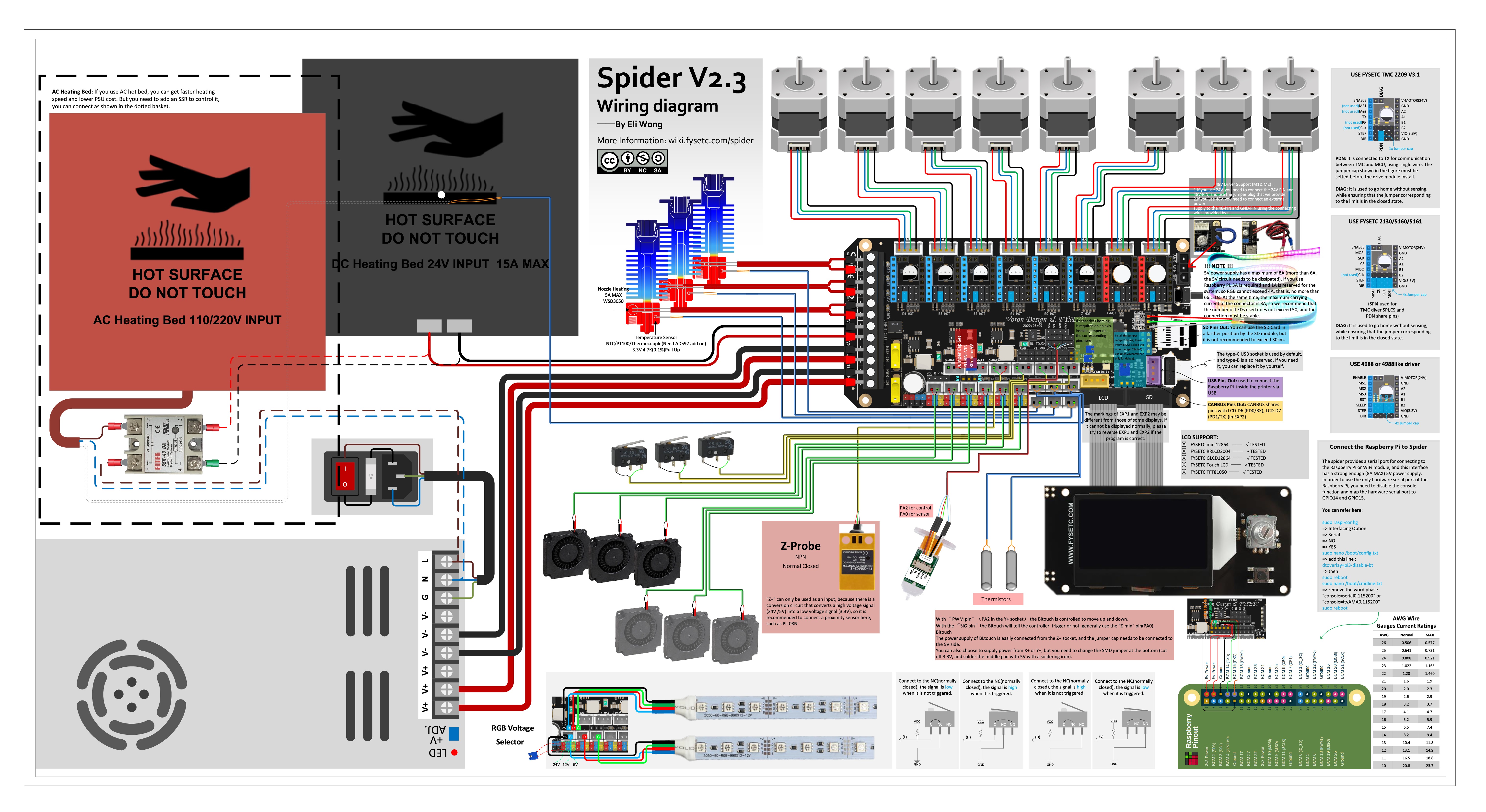
Spider v2.3 wiring for VORON 2.4
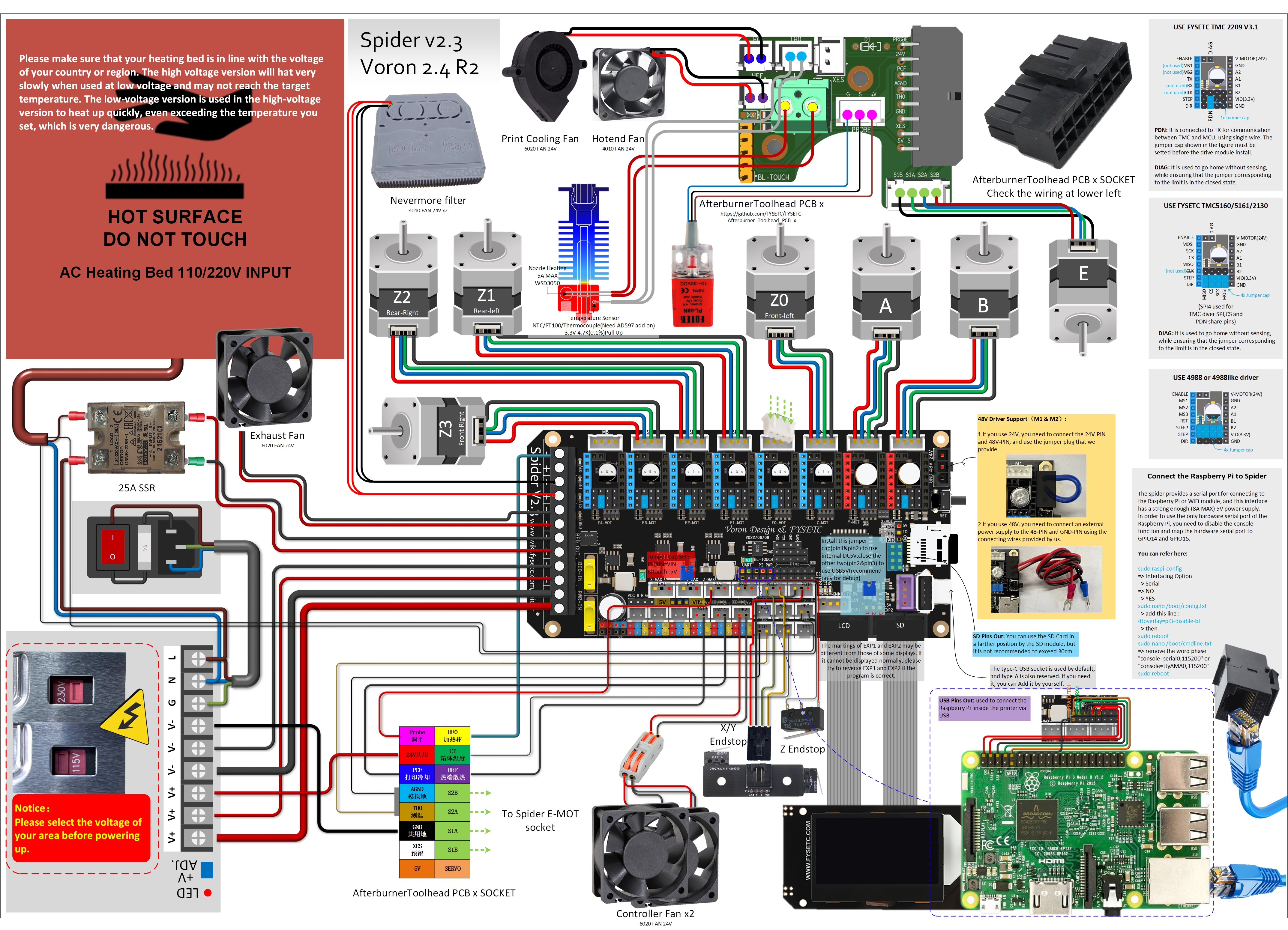
Spider v2.3 wiring for VORON Trident
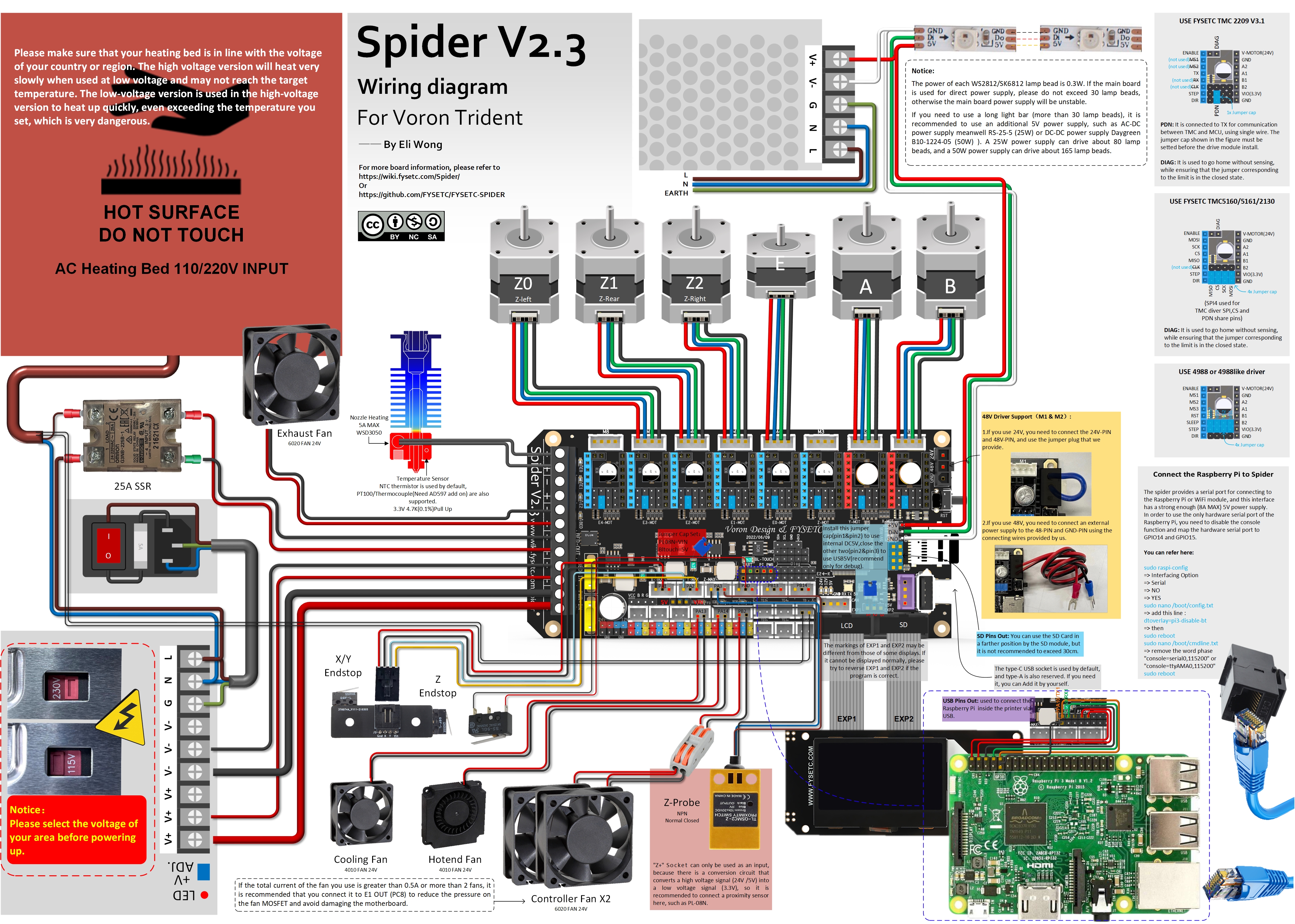
Spider v2.3 Afterburner Toolhead wiring
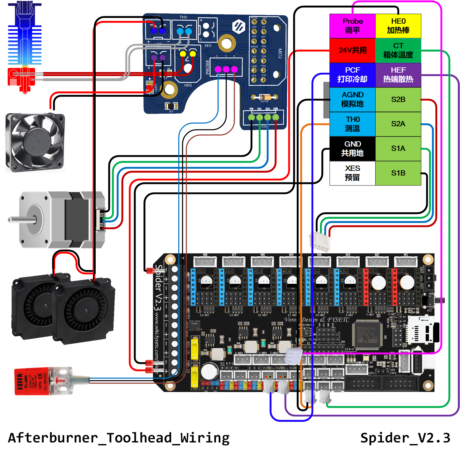
3.1.5 Spider v3.0 wiring
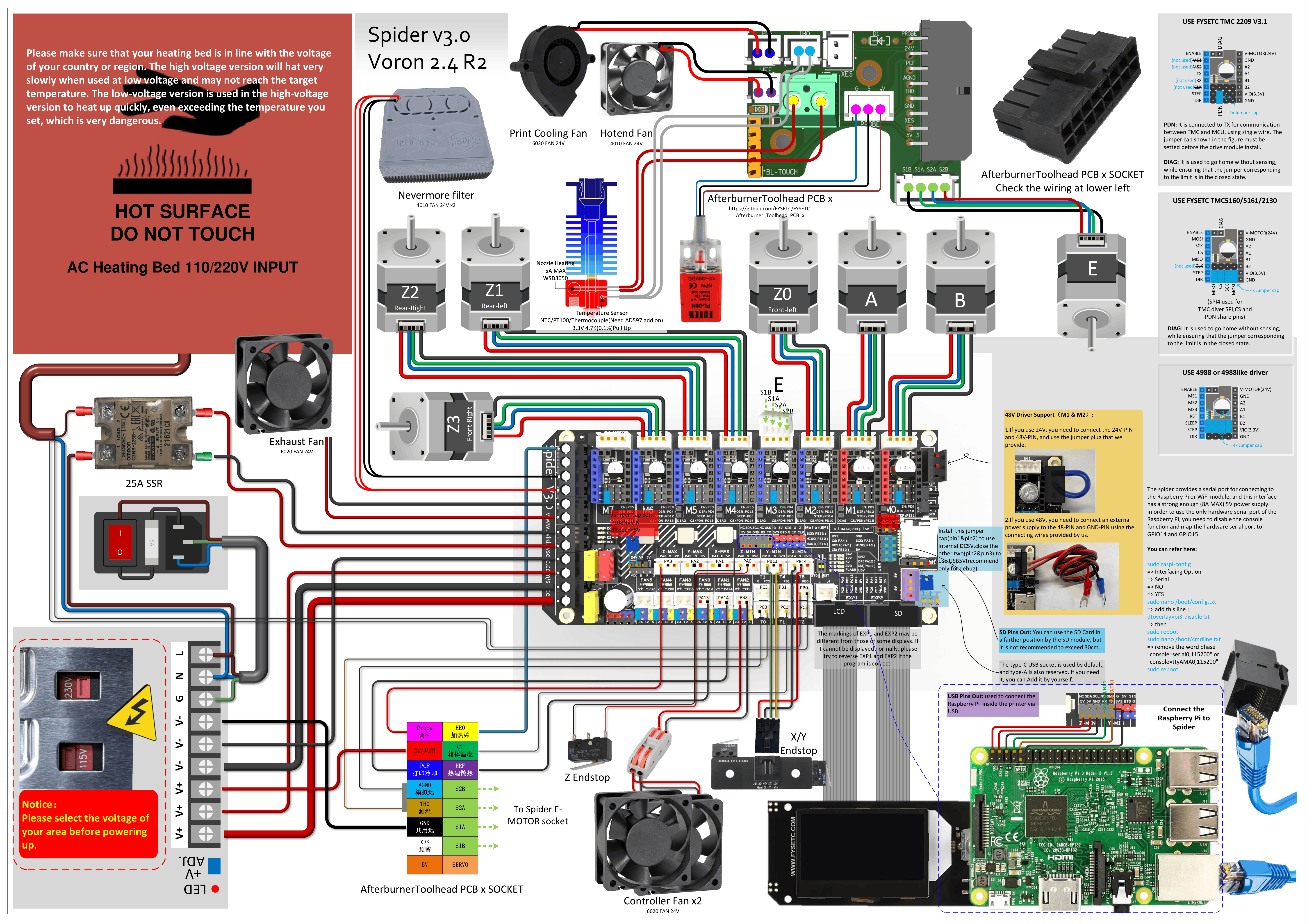
Spider v3.0 wiring for VORON 2.4
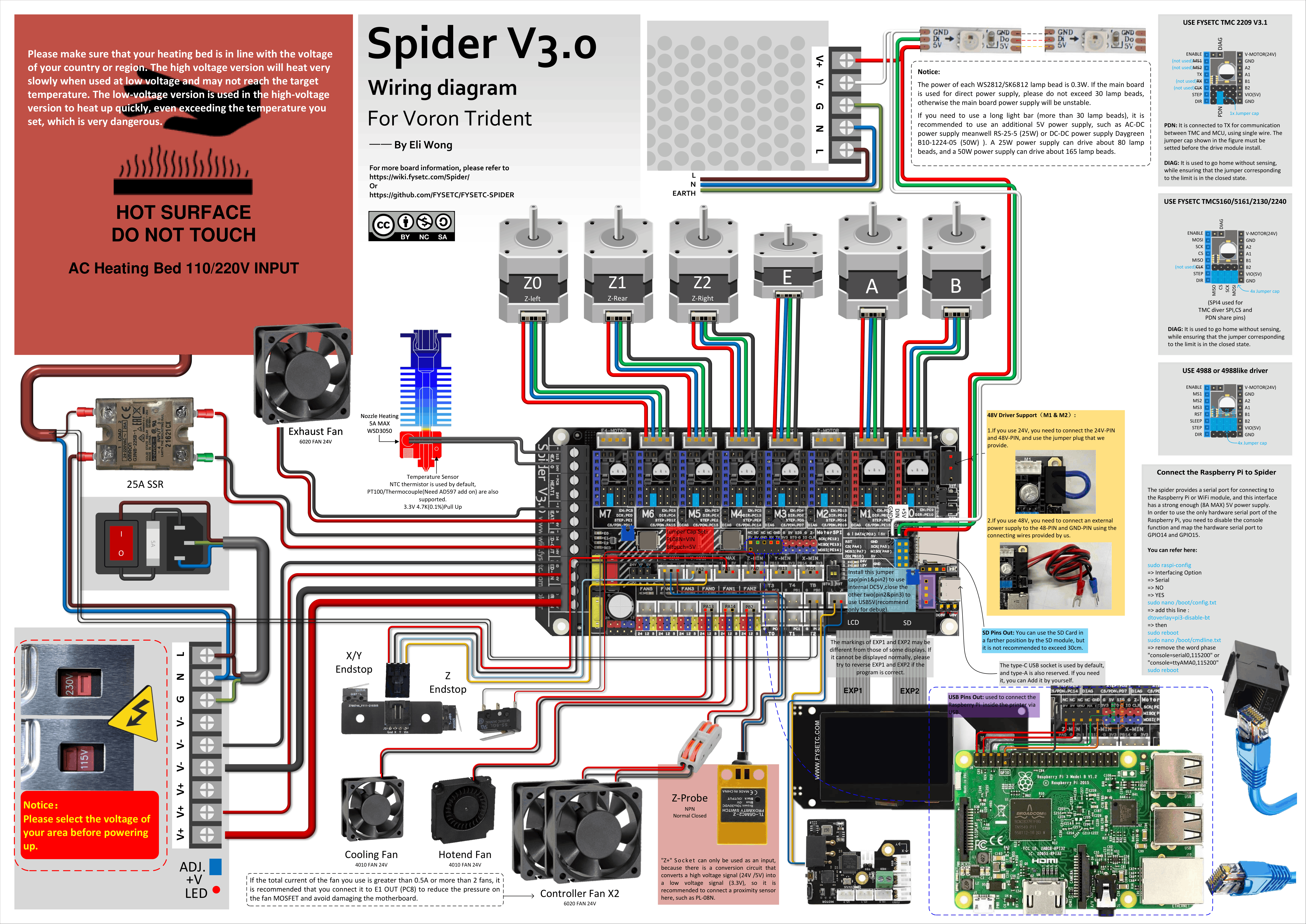
Spider v3.0 wiring for VORON Trident
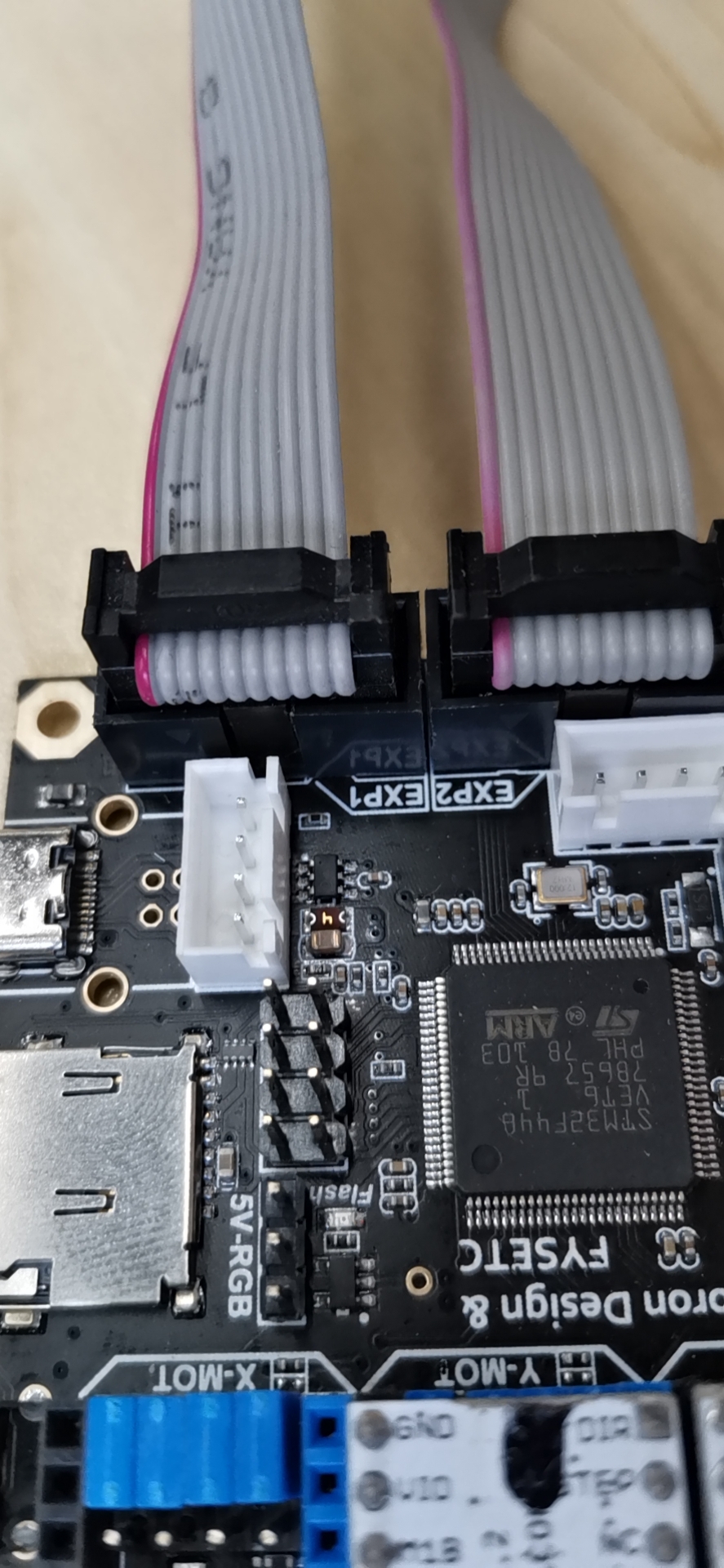
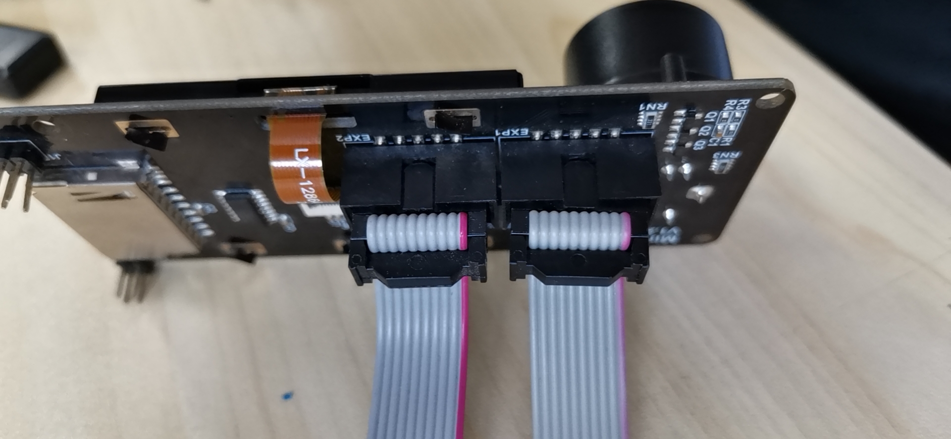
3.2 Wiring : FYSETC mini 12864 v2.1
NOTICE:
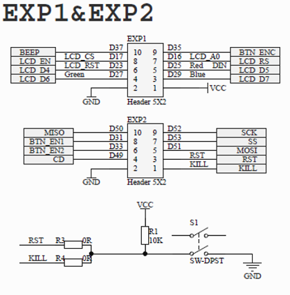
In order to be compatible with some motherboards, such as RAMPS1.4, mini12864 is equipped with RST (R3) and KILL (R4) optional resistors. At present, some motherboards (S6/Spider) change the KILL to 5V. At this time, please make sure that R4 is not on the mini12864 (please remove it if it is on the board), otherwise pressing the button on the screen will cause a short circuit between 5V and GND, and long-term operation will cause the motherboard to be damaged.
At the moment , some Spider can't upload the firmware using USB if mini12864 is connected to the board, if you run into this issue, please remove R1 resistor.
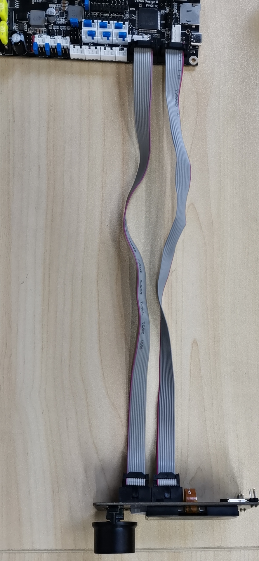
Wiring
|
|
|---|
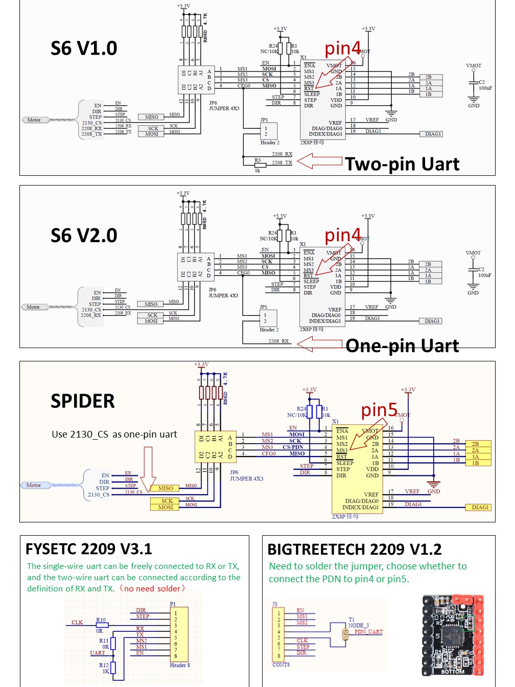
3.3 Wiring : TMC2209
3.4 Wiring
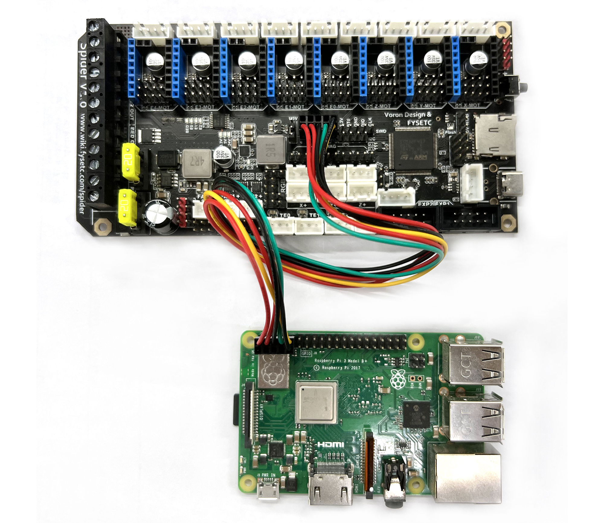
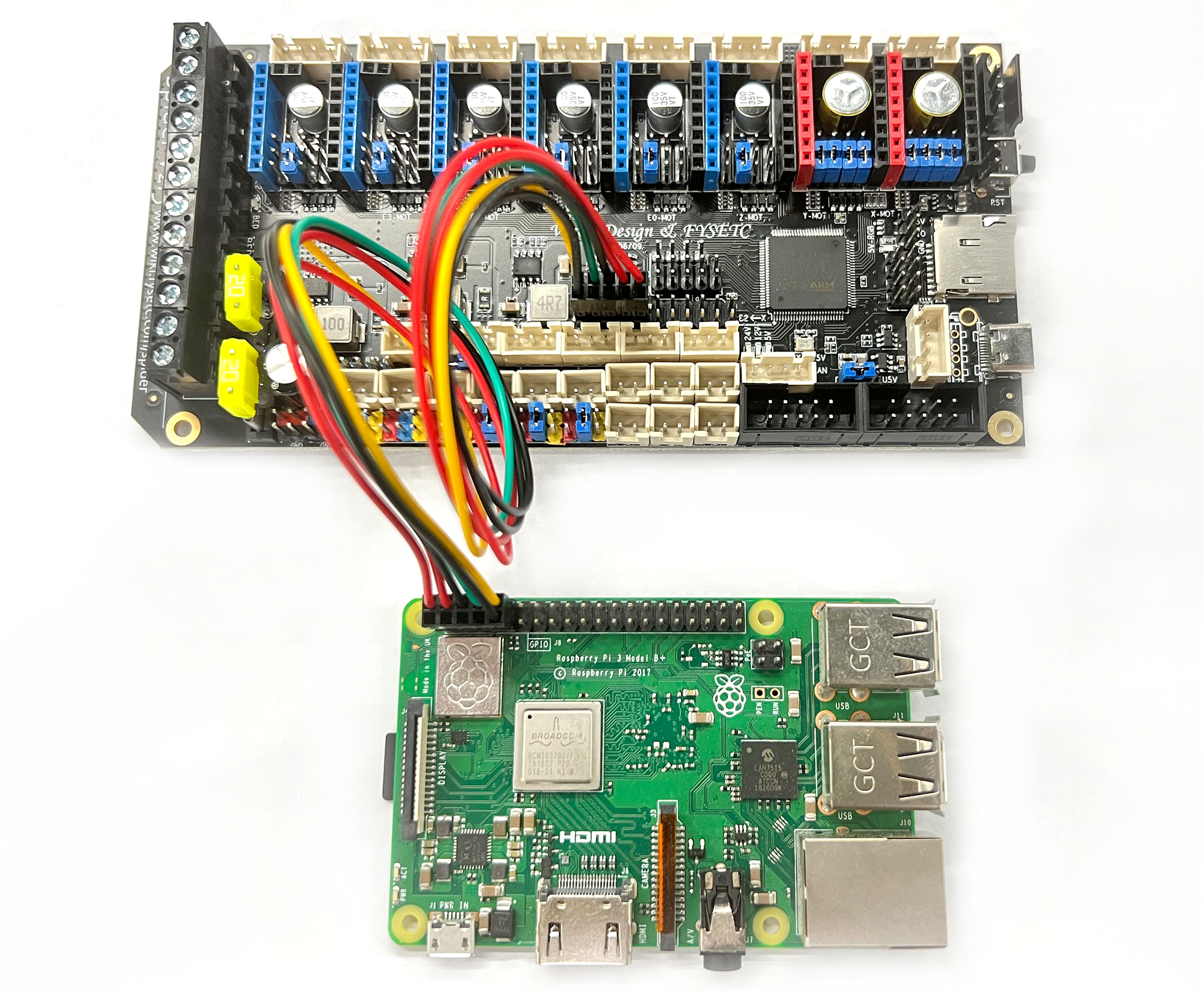
3.4.1 Raspberry Pi
Spider 1.x, Spider 2.2, Spider 3.0
Spider 2.3
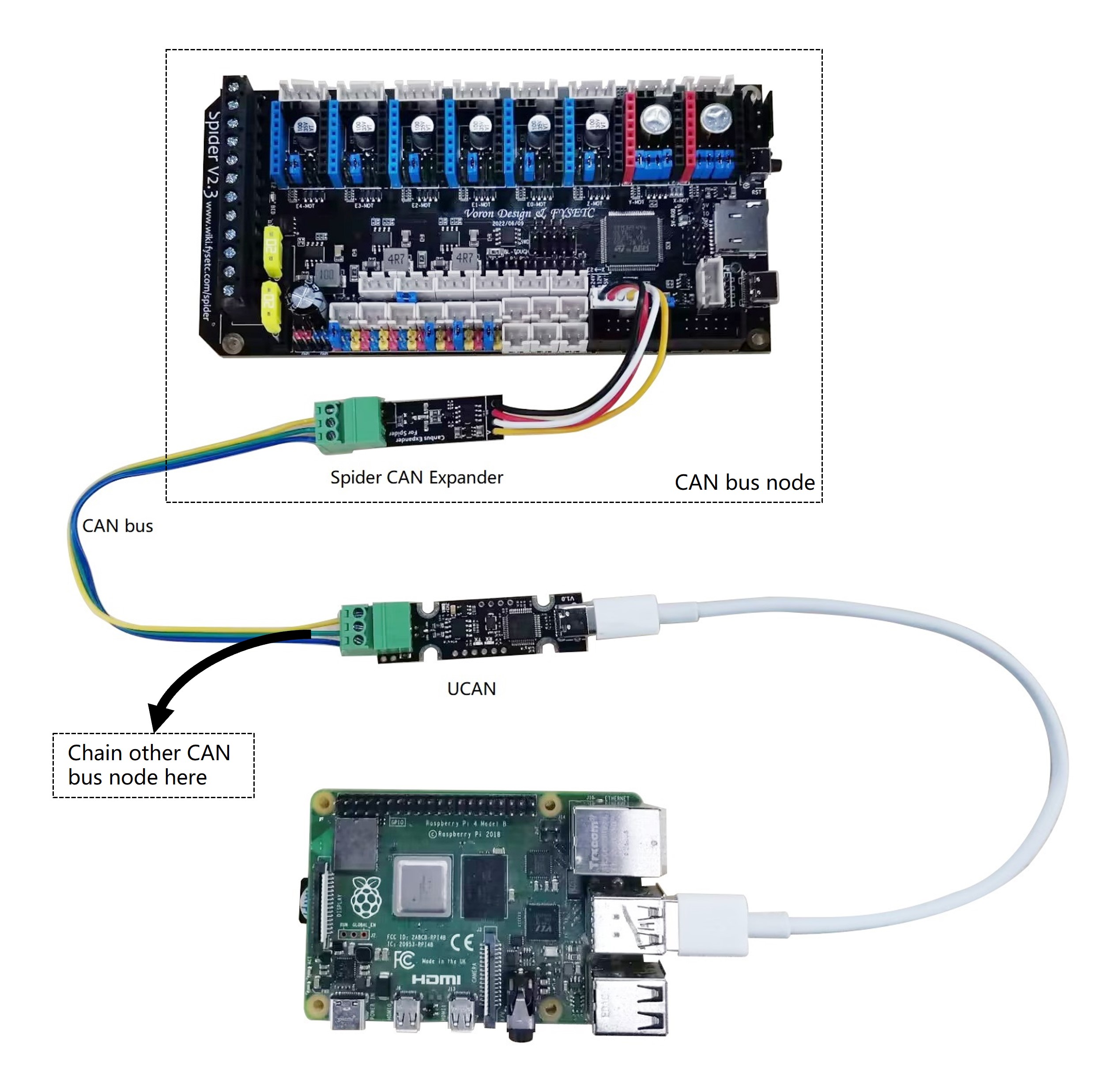
3.4.2 CAN
If you want to enable a CANBUS network in klipper on the Spider board, please check 4.2.1 chapter Communication interface section.
Spider 2.x
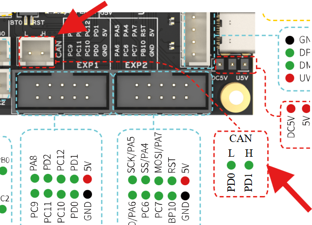
Spider 3.0
The Spider v3.0 has an internal CAN transciever, There is a permanent 120 ohm termination resistor soldered to the board, no need to add a jumper to enable it and also no ability to disable it.
The CAN port is a JST-XH header located here;
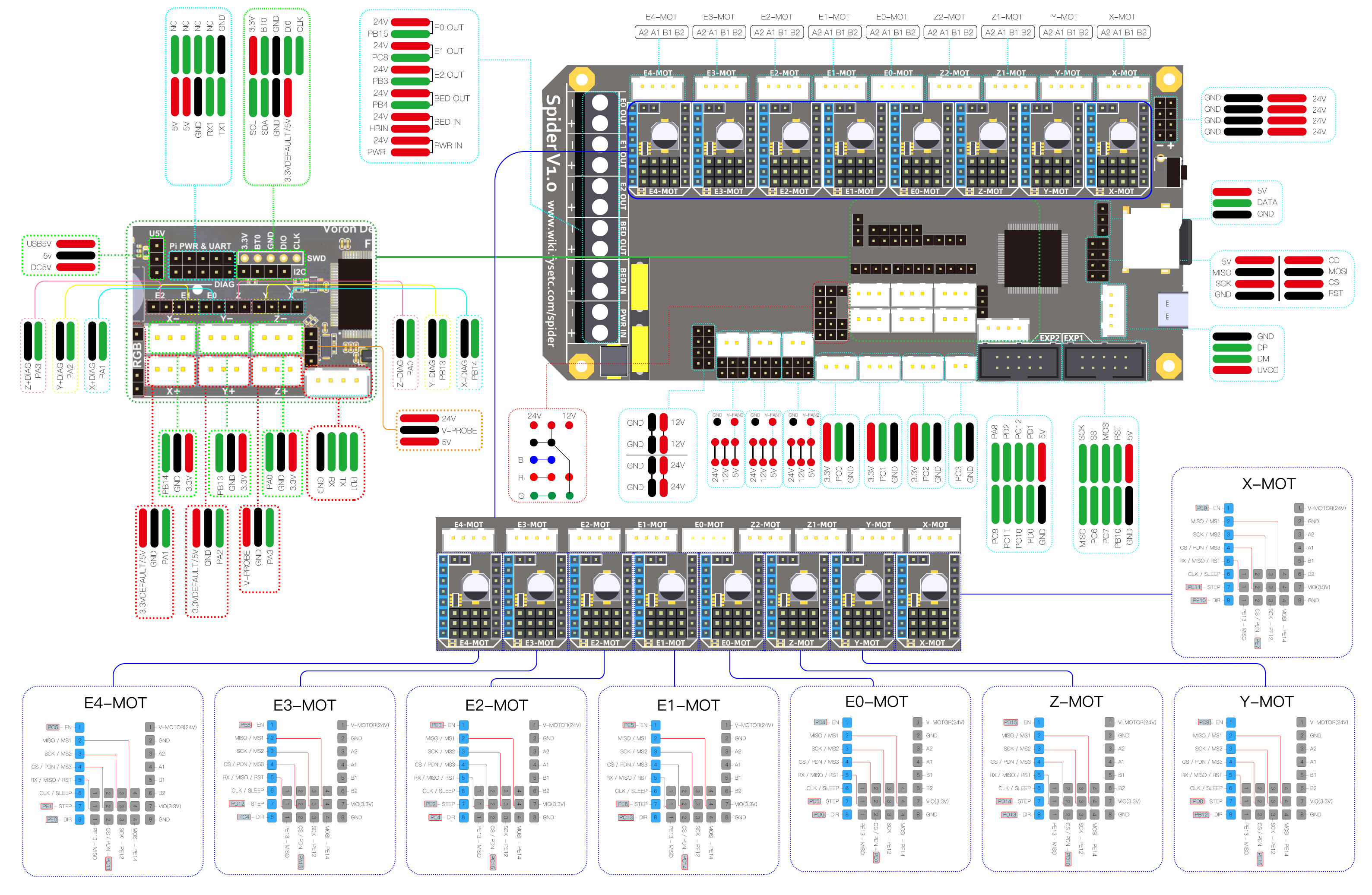
3.5 Pin Out
3.5.1 Spider v1.x
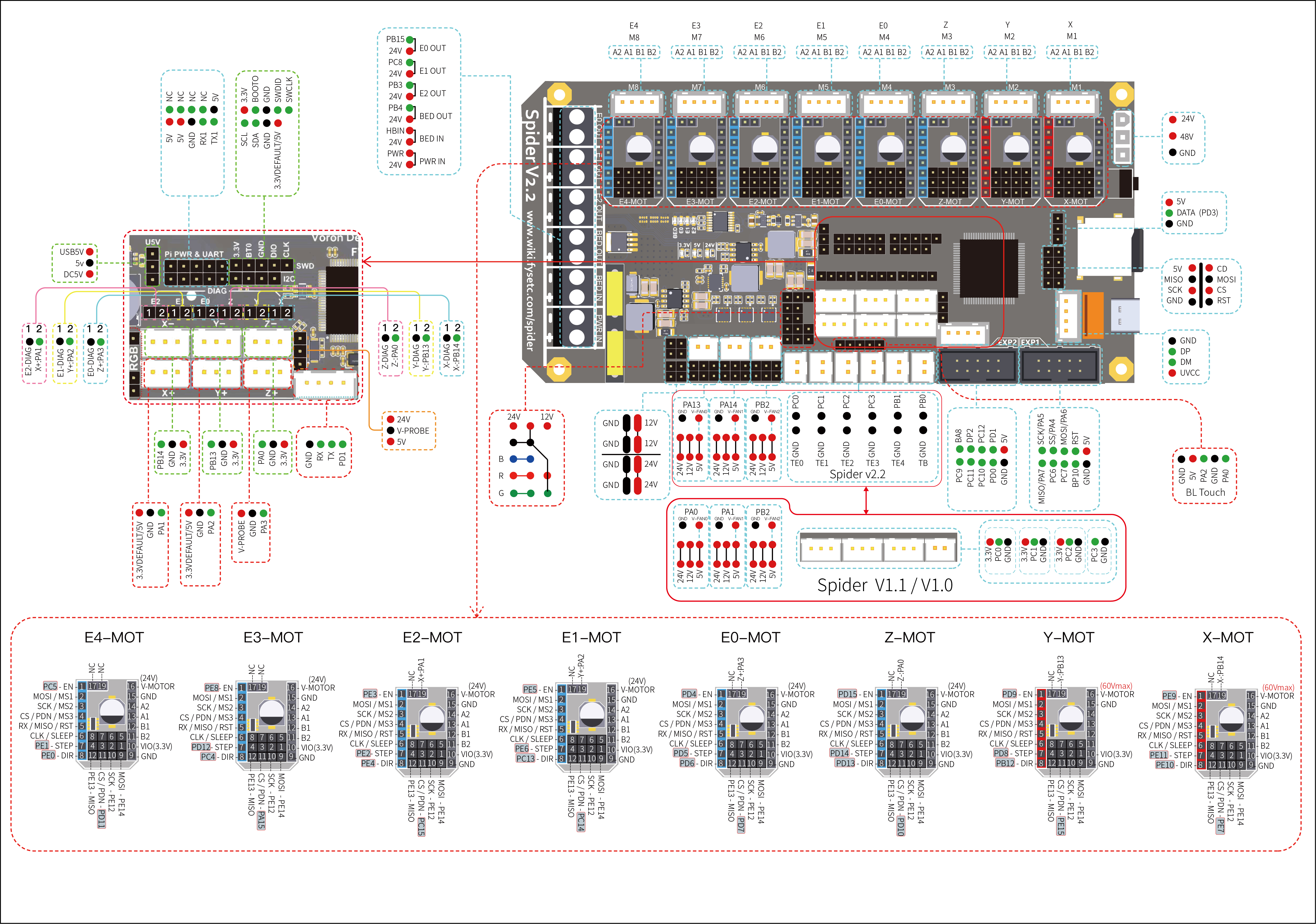
3.5.2 Spider v2.2
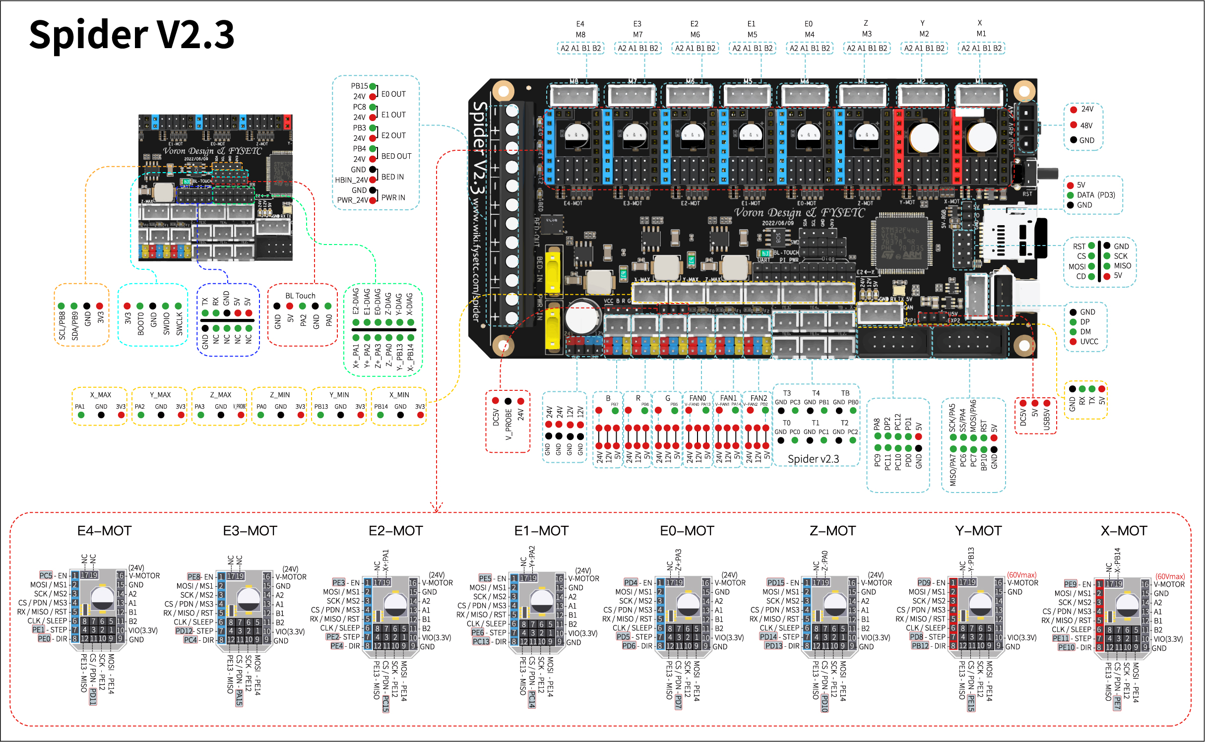
3.5.3 Spider v2.3
3.5.4 Spider v3.0

3.6 Pin Definition
3.6.1 Spider v1.x
Features | Spider Pin | STM32 Pin | Pin No. | Comment |
|---|---|---|---|---|
X-MOTOR(1) | X-Step | PE11 | 42 | |
X-MOTOR(1) | X-DIR | PE10 | 41 | |
X-MOTOR(1) | X-EN | PE9 | 40 | |
X-MOTOR(1) | X-CS/PDN | PE7 | 38 | |
Y-MOTOR(2) | Y-Step | PD8 | 55 | |
Y-MOTOR(2) | Y-DIR | PB12 | 51 | |
Y-MOTOR(2) | Y-EN | PD9 | 56 | |
Y-MOTOR(2) | Y-CS/PDN | PE15 | 46 | |
Z-MOTOR(3) | Z-Step | PD14 | 61 | |
Z-MOTOR(3) | Z-DIR | PD13 | 60 | |
Z-MOTOR(3) | Z-EN | PD15 | 62 | |
Z-MOTOR(3) | Z-CS/PDN | PD10 | 57 | |
E0-MOTOR(4) | E0-Step | PD5 | 86 | |
E0-MOTOR(4) | E0-DIR | PD6 | 87 | |
E0-MOTOR(4) | E0-EN | PD4 | 85 | |
E0-MOTOR(4) | E0-CS/PDN | PD7 | 88 | |
E1-MOTOR(5) | E1-Step | PE6 | 5 | |
E1-MOTOR(5) | E1-DIR | PC13 | 7 | |
E1-MOTOR(5) | E1-EN | PE5 | 4 | |
E1-MOTOR(5) | E1-CS/PDN | PC14 | 8 | |
E2-MOTOR(6) | E2-Step | PE2 | 1 | |
E2-MOTOR(6) | E2-DIR | PE4 | 3 | |
E2-MOTOR(6) | E2-EN | PE3 | 2 | |
E2-MOTOR(6) | E2-CS/PDN | PC15 | 9 | |
E3-MOTOR(7) | E3-Step | PD12 | 39 | |
E3-MOTOR(7) | E3-DIR | PC4 | 33 | |
E3-MOTOR(7) | E3-EN | PE8 | 59 | |
E3-MOTOR(7) | E3-CS/PDN | PA15 | 77 | |
E4-MOTOR ( 8 ) | E4-Step | PE1 | 34 | |
E4-MOTOR ( 8 ) | E4-DIR | PE0 | 97 | |
E4-MOTOR ( 8 ) | E4-EN | PC5 | 98 | |
E4-MOTOR ( 8 ) | E4-CS/PDN | PD11 | 58 | |
TMC Driver SPI (SPI4) | MOSI | PE14 | 45 | |
TMC Driver SPI (SPI4) | MISO | PE13 | 44 | |
TMC Driver SPI (SPI4) | SCK | PE12 | 43 | |
End-stops | X-MIN | PB14 | 53 | Share with X-DIAG |
End-stops | X-MAX | PA1 | 24 | Share with E0-DIAG |
End-stops | Y-MIN | PB13 | 52 | Share with Y-DIAG |
End-stops | Y-MAX | PA2 | 25 | Share with E1-DIAG |
End-stops | Z-MIN | PA0 | 23 | Share with Z-DIAG |
End-stops | Z-MAX(Probe) | PA3 | 26 | Share with E2-DIAG |
FAN/RGB | FAN0 | PB0 | 35 | |
FAN/RGB | FAN1 | PB1 | 36 | |
FAN/RGB | FAN2 | PB2/BOOT1 | 37 | |
FAN/RGB | LED-R | PB6 | 92 | Can be used for fan3 |
FAN/RGB | LED-G | PB5 | 91 | Can be used for fan4 |
FAN/RGB | LED-B | PB7 | 93 | Can be used for fan5 |
FAN/RGB | 5V-LED(WS2812) | PD3 | 84 | Share with flash indicator(Bootloader) |
Heating | E0-Heater | PB15 | 54 | |
Heating | E1-Heater | PC8 | 65 | |
Heating | E2-Heater | PB3 | 89 | |
Heating | Heated-Bed | PB4 | 90 | |
Temperature | TE0(THERM0) | PC0 | 15 | A 4.7kOhm 0.1% temperature sensor pull up resistor is used,PT1000 can be connected directly. For PT100, an amplifier board must be used. |
Temperature | TE1(THERM1) | PC1 | 16 | A 4.7kOhm 0.1% temperature sensor pull up resistor is used,PT1000 can be connected directly. For PT100, an amplifier board must be used. |
Temperature | TE2(THERM2) | PC2 | 17 | A 4.7kOhm 0.1% temperature sensor pull up resistor is used,PT1000 can be connected directly. For PT100, an amplifier board must be used. |
Temperature | TB(THERM3) | PC3 | 18 | A 4.7kOhm 0.1% temperature sensor pull up resistor is used,PT1000 can be connected directly. For PT100, an amplifier board must be used. |
EXP2 | LCD_D7 | PD1/CAN-TX1 | 82 | Share with CAN-TX1 |
EXP2 | LCD_D6 | PD0/CAN-RX1 | 81 | Share with CAN-RX1 |
EXP2 | LCD_D5 | PC12/MOSI3/TX5/SDA2 | 80 | |
EXP2 | LCD_D4 | PC10/SCK3/TX3/4 | 78 | |
EXP2 | LCD_EN | PC11/MISO3/RX3/4 | 79 | |
EXP2 | LCD_RS | PD2/RX5 | 83 | |
EXP2 | ENC_C | PA8/SCL3 | 67 | |
EXP2 | BEEP | PC9/SDA3 | 66 | |
EXP1 | RESET | NRST | 14 | |
EXP1 | ENC_A | PC6/TX6 | 63 | |
EXP1 | ENC_B | PC7/RX6 | 64 | |
EXP1 | SD-DET | PB10/SCL2 | 47 | |
EXP1 | SD-MISO | PA6/MISO1 | 31 | |
EXP1 | SD-MOSI | PA7/MOSI1 | 32 | |
EXP1 | SCK | PA5/SCK1 | 30 | |
EXP1 | CS | PA4/CS1 | 29 | |
EEPROM(4K) I2C Pin-Out | SCL | PB8/SCL1 | 95 | Connect to 24LC32(4K EEPROM) |
EEPROM(4K) I2C Pin-Out | SDA | PB9/SDA1 | 96 | Connect to 24LC32(4K EEPROM) |
Pi_PWR/UART | TX | PA9/TX1 | 68 | |
Pi_PWR/UART | RX | PA10/RX1 | 69 | |
SWD Debug | PA13/SWDIO | 72 | only used for debugging now and can be used for other purposes. | |
SWD Debug | PA14/SWCLK | 76 | only used for debugging now and can be used for other purposes. |
3.6.2 Spider v2.x, v3.x
Features | Spider Pin | STM32 Pin | Pin No. | Comment |
|---|---|---|---|---|
X-MOTOR(1) | X-Step | PE11 | 42 | |
X-MOTOR(1) | X-DIR | PE10 | 41 | |
X-MOTOR(1) | X-EN | PE9 | 40 | |
X-MOTOR(1) | X-CS/PDN | PE7 | 38 | |
Y-MOTOR(2) | Y-Step | PD8 | 55 | |
Y-MOTOR(2) | Y-DIR | PB12 | 51 | |
Y-MOTOR(2) | Y-EN | PD9 | 56 | |
Y-MOTOR(2) | Y-CS/PDN | PE15 | 46 | |
Z-MOTOR(3) | Z-Step | PD14 | 61 | |
Z-MOTOR(3) | Z-DIR | PD13 | 60 | |
Z-MOTOR(3) | Z-EN | PD15 | 62 | |
Z-MOTOR(3) | Z-CS/PDN | PD10 | 57 | |
E0-MOTOR(4) | E0-Step | PD5 | 86 | |
E0-MOTOR(4) | E0-DIR | PD6 | 87 | |
E0-MOTOR(4) | E0-EN | PD4 | 85 | |
E0-MOTOR(4) | E0-CS/PDN | PD7 | 88 | |
E1-MOTOR(5) | E1-Step | PE6 | 5 | |
E1-MOTOR(5) | E1-DIR | PC13 | 7 | |
E1-MOTOR(5) | E1-EN | PE5 | 4 | |
E1-MOTOR(5) | E1-CS/PDN | PC14 | 8 | |
E2-MOTOR(6) | E2-Step | PE2 | 1 | |
E2-MOTOR(6) | E2-DIR | PE4 | 3 | |
E2-MOTOR(6) | E2-EN | PE3 | 2 | |
E2-MOTOR(6) | E2-CS/PDN | PC15 | 9 | |
E3-MOTOR(7) | E3-Step | PD12 | 39 | |
E3-MOTOR(7) | E3-DIR | PC4 | 33 | |
E3-MOTOR(7) | E3-EN | PE8 | 59 | |
E3-MOTOR(7) | E3-CS/PDN | PA15 | 77 | |
E4-MOTOR( 8 ) | E4-Step | PE1 | 34 | |
E4-MOTOR( 8 ) | E4-DIR | PE0 | 97 | |
E4-MOTOR( 8 ) | E4-EN | PC5 | 98 | |
E4-MOTOR( 8 ) | E4-CS/PDN | PD11 | 58 | |
TMC Driver SPI (SPI4) | MOSI | PE14 | 45 | |
TMC Driver SPI (SPI4) | MISO | PE13 | 44 | |
TMC Driver SPI (SPI4) | SCK | PE12 | 43 | |
End-stops | X-MIN | PB14 | 53 | Share with X-DIAG |
End-stops | X-MAX | PA1 | 24 | Share with E0-DIAG |
End-stops | Y-MIN | PB13 | 52 | Share with Y-DIAG |
End-stops | Y-MAX | PA2 | 25 | Share with E1-DIAG |
End-stops | Z-MIN | PA0 | 23 | Share with Z-DIAG |
End-stops | Z-MAX(Probe) | PA3 | 26 | Share with E2-DIAG |
FAN/RGB | FAN0 | PA13 | 72 | |
FAN/RGB | FAN1 | PA14 | 76 | |
FAN/RGB | FAN2 | PB2/BOOT1 | 37 | |
FAN/RGB | LED-R | PB6 | 92 | Can be used for fan3 |
FAN/RGB | LED-G | PB5 | 91 | Can be used for fan4 |
FAN/RGB | LED-B | PB7 | 93 | Can be used for fan5 |
FAN/RGB | 5V-LED(WS2812) | PD3 | 84 | Share with flash indicator(Bootloader) |
Heating | E0-Heater | PB15 | 54 | |
Heating | E1-Heater | PC8 | 65 | |
Heating | E2-Heater | PB3 | 89 | |
Heating | Heated-Bed | PB4 | 90 | |
Temperature | TE0(THERM0) | PC0 | 15 | A 4.7kOhm 0.1% temperature sensor pull up resistor is used,PT1000 can be connected directly. For PT100, an amplifier board must be used. |
Temperature | TE1(THERM1) | PC1 | 16 | A 4.7kOhm 0.1% temperature sensor pull up resistor is used,PT1000 can be connected directly. For PT100, an amplifier board must be used. |
Temperature | TE2(THERM2) | PC2 | 17 | A 4.7kOhm 0.1% temperature sensor pull up resistor is used,PT1000 can be connected directly. For PT100, an amplifier board must be used. |
Temperature | TE3(THERM3) | PC3 | 18 | A 4.7kOhm 0.1% temperature sensor pull up resistor is used,PT1000 can be connected directly. For PT100, an amplifier board must be used. |
Temperature | TE4(THERM4) | PB1 | 36 | A 4.7kOhm 0.1% temperature sensor pull up resistor is used,PT1000 can be connected directly. For PT100, an amplifier board must be used. |
Temperature | TB(THERM3) | PB0 | 35 | A 4.7kOhm 0.1% temperature sensor pull up resistor is used,PT1000 can be connected directly. For PT100, an amplifier board must be used. |
EXP2 | LCD_D7 | PD1/CAN-TX1 | 82 | Share with CAN-TX1 |
EXP2 | LCD_D6 | PD0/CAN-RX1 | 81 | Share with CAN-RX1 |
EXP2 | LCD_D5 | PC12/MOSI3/TX5/SDA2 | 80 | |
EXP2 | LCD_D4 | PC10/SCK3/TX3/4 | 78 | |
EXP2 | LCD_EN | PC11/MISO3/RX3/4 | 79 | |
EXP2 | LCD_RS | PD2/RX5 | 83 | |
EXP2 | ENC_C | PA8/SCL3 | 67 | |
EXP2 | BEEP | PC9/SDA3 | 66 | |
EXP1 | RESET | NRST | 14 | |
EXP1 | ENC_A | PC6/TX6 | 63 | |
EXP1 | ENC_B | PC7/RX6 | 64 | |
EXP1 | SD-DET | PB10/SCL2 | 47 | |
EXP1 | SD-MISO | PA6/MISO1 | 31 | |
EXP1 | SD-MOSI | PA7/MOSI1 | 32 | |
EXP1 | SCK | PA5/SCK1 | 30 | |
EXP1 | CS | PA4/CS1 | 29 | |
EEPROM(4K) I2C Pin-Out | SCL | PB8/SCL1 | 95 | Connect to 24LC32(4K EEPROM) |
EEPROM(4K) I2C Pin-Out | SDA | PB9/SDA1 | 96 | Connect to 24LC32(4K EEPROM) |
Pi_PWR/UART | TX | PA9/TX1 | 68 | |
Pi_PWR/UART | RX | PA10/RX1 | 69 | |
SWD Debug | PA13/SWDIO | 72 | only used for debugging now and can be used for other purposes. | |
SWD Debug | PA14/SWCLK | 76 | only used for debugging now and can be used for other purposes. |
4. Firmware Guide
Spider support Marlin firmware, Klipper firmware and RRF firmware. Choose one you need.
4.1 Marlin
4.1.1 Download Vscode + platformio
To compile the firmware , you need to install Visual Studio Code and the platformio pulg-in.
4.1.2 Download firmware
The Marlin firmware is in the firmware/Marlin folder in this repository , you can also get the firmware from latest Marlin bugfix-2.0.x branch. You need to enable following define in configuration.h file
#define MOTHERBOARD BOARD_FYSETC_SPIDER
#define SERIAL_PORT -1
Then we need to change platformio.ini file
default_envs = FYSETC_S6 (For old bootloader,boot address is 0x10000, see below)
default_envs = FYSETC_S6_8000 (For new bootloader,boot address is 0x8000, see below)
Note: The bootloader boot address have been change to 0x08008000 since 2021/06/23, you can check bootloader details github or gitee, and you can check the Marlin PR here.
4.1.3 Compile the firmware
Open Vscode and open platformio main page and click the "Open Project" button , and direct to the folder where you put your firmware.
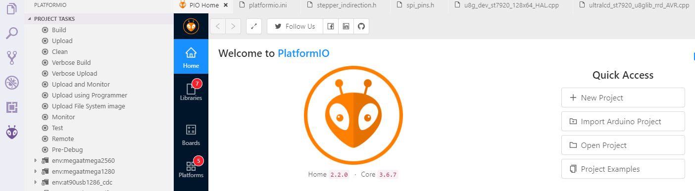
If everything goes fine , at the bottom you can see several buttons

The check mark is for compiling , click it to compile. You can find built firmware.bin at .pio\build\FYSETC_S6 or .pio\build\FYSETC_S6_8000 folder.
4.1.4 Upload firmware
Follow Firmware Update guide here.
4.2 Klipper
We put Klipper related files like printer.cfg in firmware/Klipper folder in this repo. Please read the README there.
If you want to use Klipper. You need to follow the Klipper installation guide to install Klipper first. When we try to compile it, we need to call make menuconfig to choose compile options, please select options for Spider as below describe.
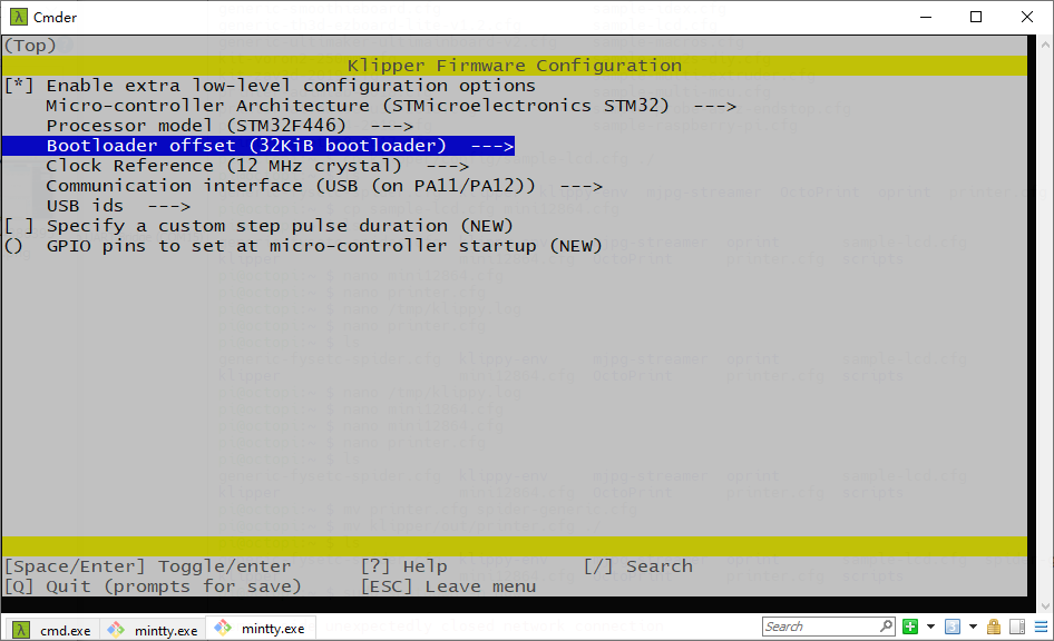
4.2.1 menuconfig
Please choose these options for Spider, you need to decide which to choose according to your board and wiring on some options.
Enable
extra low-level configuration optionsMicro-controller Architecture
Select STMicroelectronics STM32
Processor model
Select STM32F446
Clock reference
Select 12 MHz crystal
Bootloader offset
32KiB bootloader
If you choose 32kiB bootloader offset in Klipper make menuconfig. Then you need to flash the spider board bootloader named Bootloader_FYSETC_SPIDER first(If you get your Spider board after 2021/06/23, no worries, the bootloader is on the board when it leave the factory, if not, flash it first). The bootloader is in the folder named bootloader in this repo, please follow the README in bootloader folder(github or gitee) to flash the bootloader. We provide pre-build firmwares with 32KiB bootloader named klipper-32k-USB.bin and klipper-32k-UART.bin for you,find them here github gitee. These pre-build firmware will be outdated if Klipper update and will not match your new downloaded Klipper and cause annoying issues. We will try to catch up with Klipper, but i recommend to build the firmware yourself.
Communication interface
You have two choices here, if you use USB cable to connect RaspeberryPI and Spider, you need to check1. USB (on PA11/PA12). If you use serial to connect RaspberryPI and Spider, then check2. Serial (on USART1 PA10/PA9).1. USB (on PA11/PA12)
If you want to connect Spider to RaspberryPI with USB cable. You need to select USB (on PA11/PA12)
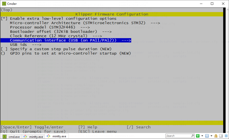
And in printer.cfg you need to set the serial as below. We provide an example cfg file printer.cfg for VORON 2 machine here.
Obtain definition by "ls -l /dev/serial/by-id/" then unplug to verify
##--------------------------------------------------------------------
serial: /dev/serial/by-id/usb-Klipper_stm32f446xx_230032000851363131363530-if00
2. Serial (on USART1 PA10/PA9)
If you want to connect Spider UART1(RX1:PA10, TX1:PA9) port to RPI uart0(TX:GPIO14,RX:GPIO15) port, you need to select Serial (on USART1 PA10/PA9)
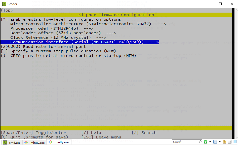
In printer.cfg you need to uncomment the following line as our example printer.cfg file here (github gitee)do, if your cfg file don't have this line, please add it.
serial: /dev/ttyAMA0Besides this make option, you still need to follow the instructions that Connect RPI ``uart.md file says, you can find the file github or gitee.
3. CAN bus (on PD0/PD1)
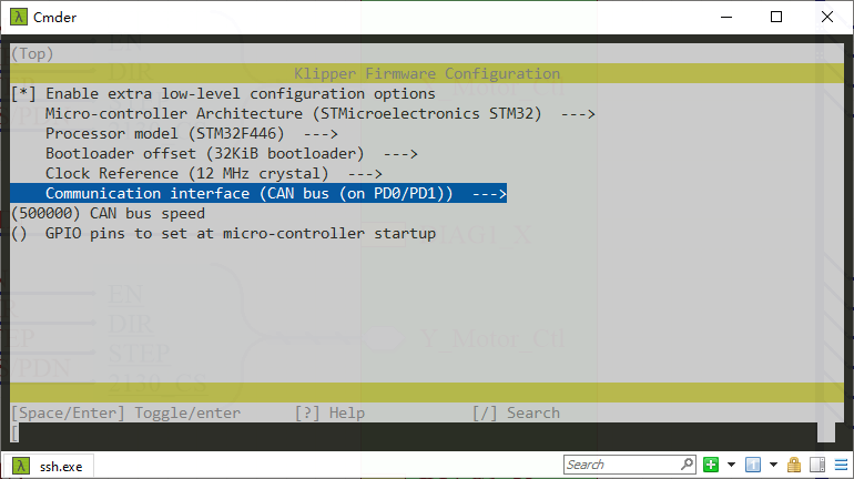
You need to follow Klipper CANBUS instruction here CANBUS - Klipper documentation after you compiled and upload the firmware.
4.2.2 Compile firmware
make4.2.3 Upload firmware
Follow Firmware Update guide here.
4.3 RRF
As RRF firmware requires more than 512KB of Flash space, the Spider equipped with 446 cannot meet its requirements. So it needs to disable some features to make it work, please check the README in firmware/RRF folder github gitee.
4.4
Firmware Upload
We provide several ways to upload the firmware including SDCARD, dfu-util, DFU and platformio.
4.4.1
Upload the firmware(SDCARD)
Uploading firmware using SD card is our default way to update the firmware as Spider already has the bootloader in it when it leave the factory. But if you once upload the firmware to Spider flash address 0x08000000, then the bootloader in Spider will be gone, then you need to upload the bootloader to Spider yourself, please follow the README in bootloader folder (github or gitee) to upload the bootloader.
Uploading firmware using SD card: copy your compiled firmware file firmware.bin(If you use klipper firmware, you need to rename klipper.bin to firmware.bin) file to the SD card , and insert it to the SD card slot which is at the right side of the board, and then power up the board. You may need to wait for about 30s to finish uploading, there is LED beside the sdcard slot blinking when it is uploading.
4.4.2
Upload the firmware(dfu-util)
This method works in linux, that means should work in raspberry pi.
Step 1. Enter DFU mode first
- First power off the board
- Set jumper on 5V pin and DC5V
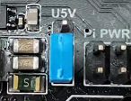
- Place jumper on BT0 to 3.3V pin
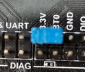
- Connect USB cable to the board and your computer
- Power up the board with 24v
Now the board is in DFU mode. If not, click the reset button. Also you can power on the board with 5v, but you need to set jumper on 5V and USB5V (Check the silkscreen lable on the back of the board) but not on 5V and DC5V.
REMEMBER to remove BT0 jumper if you finish uploading firmware or it will enter DFU mode again.
Step 2. Install dfu-util
Make sure dfu-util is installed, shoot dfu-util --version command to check.
Sample output:
dfu-util 0.9

Copyright 2005-2009 Weston Schmidt, Harald Welte and OpenMoko Inc.
Copyright 2010-2016 Tormod Volden and Stefan Schmidt
This program is Free Software and has ABSOLUTELY NO WARRANTY
Please report bugs to http://sourceforge.net/p/dfu-util/tickets/
If not , you should install it first, use the package manager of your distribution to get the latest version, like
sudo apt-get install dfu-utilStep 3. Use command to upload firmware
Then use the command below to upload the firmware. You should replace firmware.bin below with your built firmware bin(or hex) file location like out/klipper.bin. Change flash address 0x08008000 to bootloader you choosed. (If you use Marlin firmware and your platformio env is default_envs = FYSETC_S6, then you need to set it to 0x08010000, if env is default_envs = FYSETC_S6_8000, then you need to set it to 0x08008000 . If you use klipper firmware and you choose boot address No bootloader when compiling then set it 0x08000000, if 32kiB bootloader , set it 0x08008000. if 64KiB bootloader set it to 0x08010000.If yours is hex file, set it 0x08000000).
dfu-util -R -a 0 -s 0x08008000:leave -D firmware.bin4.4.3
Upload the firmware(DFU)
The other way to upload the firmware is using DFU.
Step 1. Download stm32cubeprogrammer
You can download it from ST website.
https://www.st.com/zh/development-tools/stm32cubeprog.html
Open the STM32CubeProgrammer software.
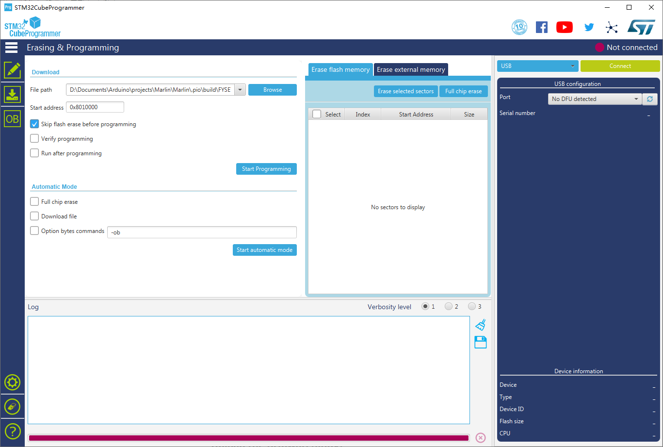
Step 2. Enter DFU mode
- First power off the board
- Set jumper on 5V pin and DC5V
- Place jumper on BT0 to 3.3V pin
- Connect USB cable to the board and your computer
- Power up the board with 24v
Now the board is in DFU mode. If not, click the reset button. Also you can power on the board with 5v, but you need to set jumper on 5V and USB5V (Check the silkscreen lable on the back of the board) but not on 5V and DC5V.
REMEMBER to remove BT0 jumper if you finish uploading firmware or it will enter DFU mode again.
Step 3. Upload the firmware
Now you can connect and flash the Spider board with stm32cubeprogrammer with the following operation.
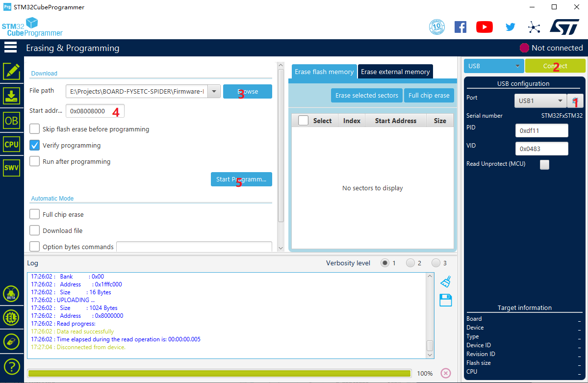
Do as the red number shows in the screen shot.
- Click the button to find the DFU port.
- Connect the DFU
- Choose the "firmware.bin" file. (or .hex file).
- Fill in the 'Start address' (If you use Marlin firmware and your platformio env is
default_envs = FYSETC_S6, then you need to set it to0x08010000, if env isdefault_envs = FYSETC_S6_8000, then you need to set it to0x08008000. If you use klipper firmware and you choose boot addressno bootloaderwhen compiling then set it0x08000000, if32kiB bootloader, set it0x08008000. if64KiB bootloaderset it to0x08010000. If yours is hex file, don't need to set anything). - Start Programming
4.4.4 Upload the firmware(platformio)
If you compile Marlin yourself with platformio,you can follow the instructions below to upload the firmware.
Step 1. Enter DFU mode first
- First power off the board
- Set jumper on 5v pin and DC5V
- Place jumper on BT0 to 3.3V pin
- Connect USB cable to the board and your computer
- Power up the board with 24v
Now the board is in DFU mode. If not, click the reset button. Also you can power on the board with 5v, but you need to set jumper on 5V and USB5V (Check the silkscreen lable on the back of the board) but not on 5V and DC5V.
REMEMBER to remove BT0 jumper if you finish uploading firmware or it will enter DFU mode again.
Step 2. Click the upload button to upload firmware

4.5 Test firmware
If you suspect there is something wrong with your board, you can use our test firmware to have a test. Follow the README here (github gitee).
5. Issue shot
5.1 Spider 3.3v issue
Please check here(github gitee).
5.2 TMC2209 connection issue
Fix 1 : Please add a jumper on each TMC2209 on your Spider board. And restart the machine again.
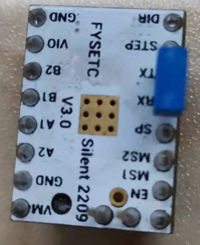
Fix 2: Try to shoot Klipper command
INIT_TMC STEPPER=name can be stepper_x,stepper_yand other stepper in your printer.cfg.
5.3 firmware.bin not changed to old.bin
Fix 1: Reflash the bootloader, follow the instruction here ( github gitee ).
Fix 2: If you use Klipper firmware, choose No bootloader option when compiling, and upload the firmware to 0x08000000 flash address. Refer to Upload the firmware(dfu-util) or Upload the firmware(DFU) chapter.
6. Where to buy
7. Tech Support
You can submit issue in our github https://github.com/FYSETC/FYSETC-SPIDER/issues
Or submit any technical issues into our Discord Server
8. Related Articles
Updated on: 03/08/2026
Thank you!