QHV5160
QHV5160
Version Notes
V1.0
1.init version
V1.0C
1.Connect DIAG0 and DIAG1 together
V1.0E
1.Changed some component packages
2.Added SD_MODE jumper pad
V2.0
1.Add resistors to protect the MOSFET.
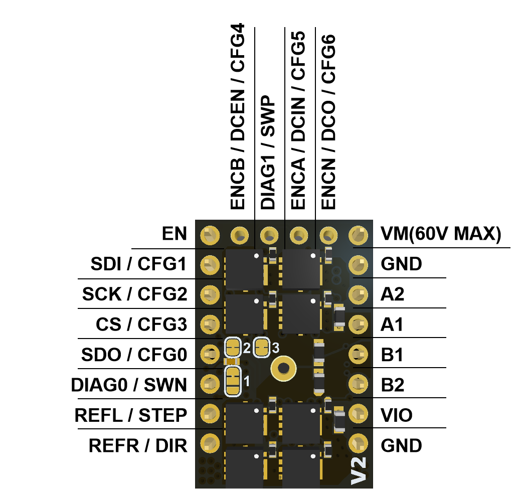
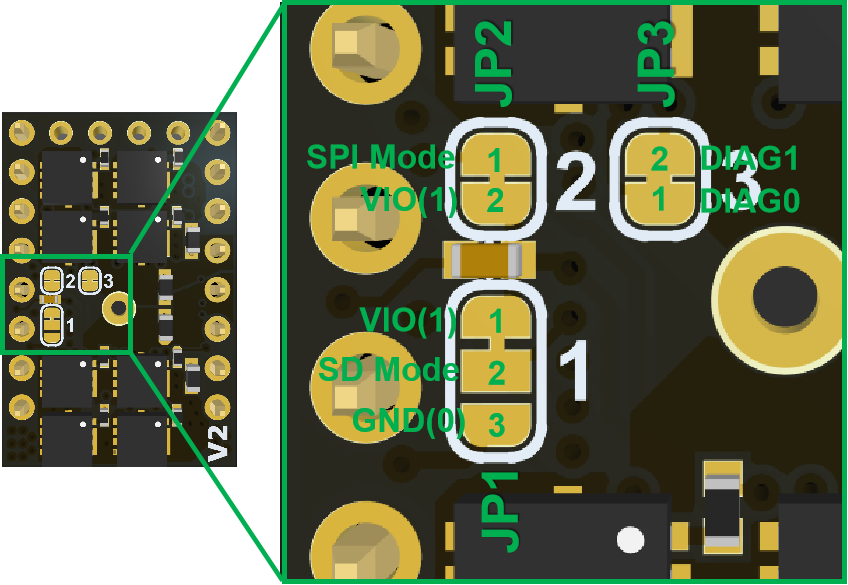
2.Add jumpers DIAG0 and DIAG1 (JP3) for serial communication selection.
3.Adjust the pinout to enable serial communication.
1. Introduction
QHV5160 is a upgrade of HV5160, specially designed for high-voltage drive requirements and can work in the voltage range of 8-60V, such as 48V. The new design uses the QFP package of TMC5160, and selects eight 3x3 low-resistance MOSFETs. and also uses Samsung Electronics’ 100V X7R ceramic capacitors
THE TMC5160 OFFERS THREE BASIC MODES OF OPERATION:
MODE 1: Full Featured Motion Controller & Driver
All stepper motor logic is completely within the TMC5160. No software is required to control the motor – just provide target positions. Enable this mode by tying low pin SD_MODE.
MODE 2: Step & Direction Driver
An external high-performance S-ramp motion controller like the TMC4361 or a central CPU generates step & direction signals synchronized to other components like additional motors within the system. The TMC5160 takes care of intelligent current and mode control and delivers feedback on the state of the motor. The MicroPlyer automatically smoothens motion. Tie SD_MODE high.
MODE 3: Simple Step & Direction Driver
The TMC5160 positions the motor based on step & direction signals. The MicroPlyer automatically smoothens motion. No CPU interaction is required; configuration is done by hardware pins. Basic standby current control can be done by the TMC5160. Optional feedback signals allow error detection and synchronization. Enable this mode by tying pin SPI_MODE low and SD_MODE high.
2. Feature
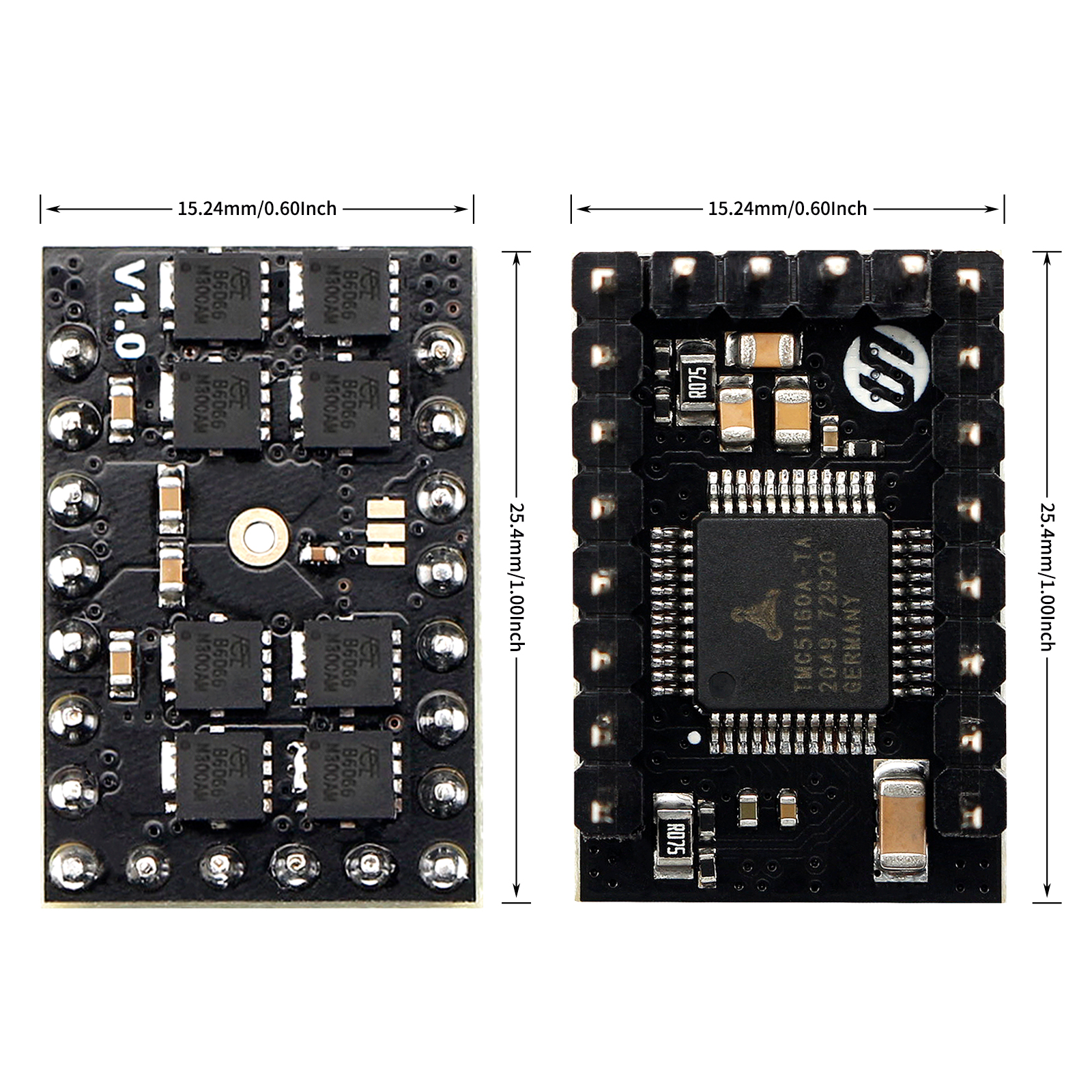
- 900 x 600mil / 22.3 x 15.24mm
- 6 layer TG155 PCB
- 8-60V 3.0A (rms) / 4.2A (peak)【Be constrained by connectors, not components.】
- 8 x NMOS (4.4 mΩ)
- Step/Dir interface & SPI mode default
- Compatible with Stepstick Pins
- Encoder Interface pinout
- DIAG output for sensorless homing
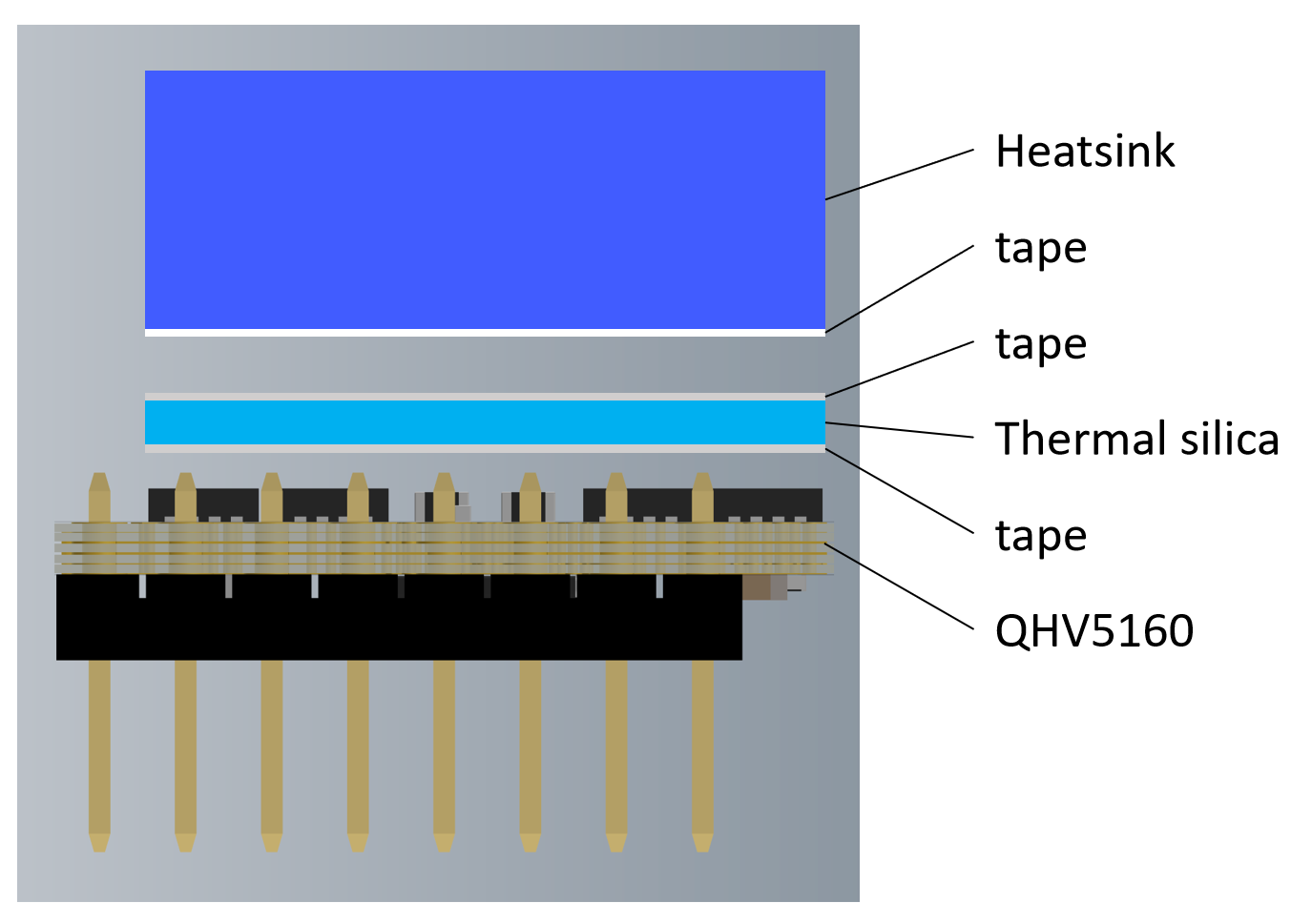
- With thermally conductive silicone and extra strong aluminum heatsink.
3. Application
3D printers, CNCs, engraving machines, or other similar devices with stepper motors.
4. Specifications
TMC5160 | HV5160 | QHV5160 | |
|---|---|---|---|
Motor Voltage (VM) | 8-40V | 8-60V | 8-60V |
Size | 800 x 600mil / 20.32 x 15.24mm | 1000 x 600mil / 25.4 x 15.24mm | 900 x 600 mil /22.3 x 15.24 |
MOSFET | 4x WSD4066 (17mΩ) | 4x DMT6018 (17 mΩ) | 8x 4.4mΩ NMOS |
Heatsink | 238.6 W/(m·K)铝散热片 | 393.6 W/(m·K)纯铜散热片 | 238.6 W/(m·K)铝散热片 |
Motor Phase Current max | 3.0A (rms) / 4.2A (peak) | ||
Rs | 0.075Ω | ||
Default Mode | SPI Mode,Standalone mode selectable via solder option | ||
PCB layer | 6 层,TG155 | ||
Pinout | DIAG0 & Encoder Interface pinout | ||
Native Microsteps | up to 1/256 | ||
microPlyer Microsteps | 1/256 | ||
Logic Voltage (VIO) | 3-5V | ||
Internal V-Regulator | enabled | ||
stealthChop (quiet) | yes | ||
spreadCycle | yes | ||
coolStep | yes | ||
stallGuard | yes | ||
dcStep | yes | ||
SPI Interface | Yes | Yes | Yes |
UART Interface | No | No | Yes (V2.0 only) |
5. Hardware Guide
5.1 Pin Out
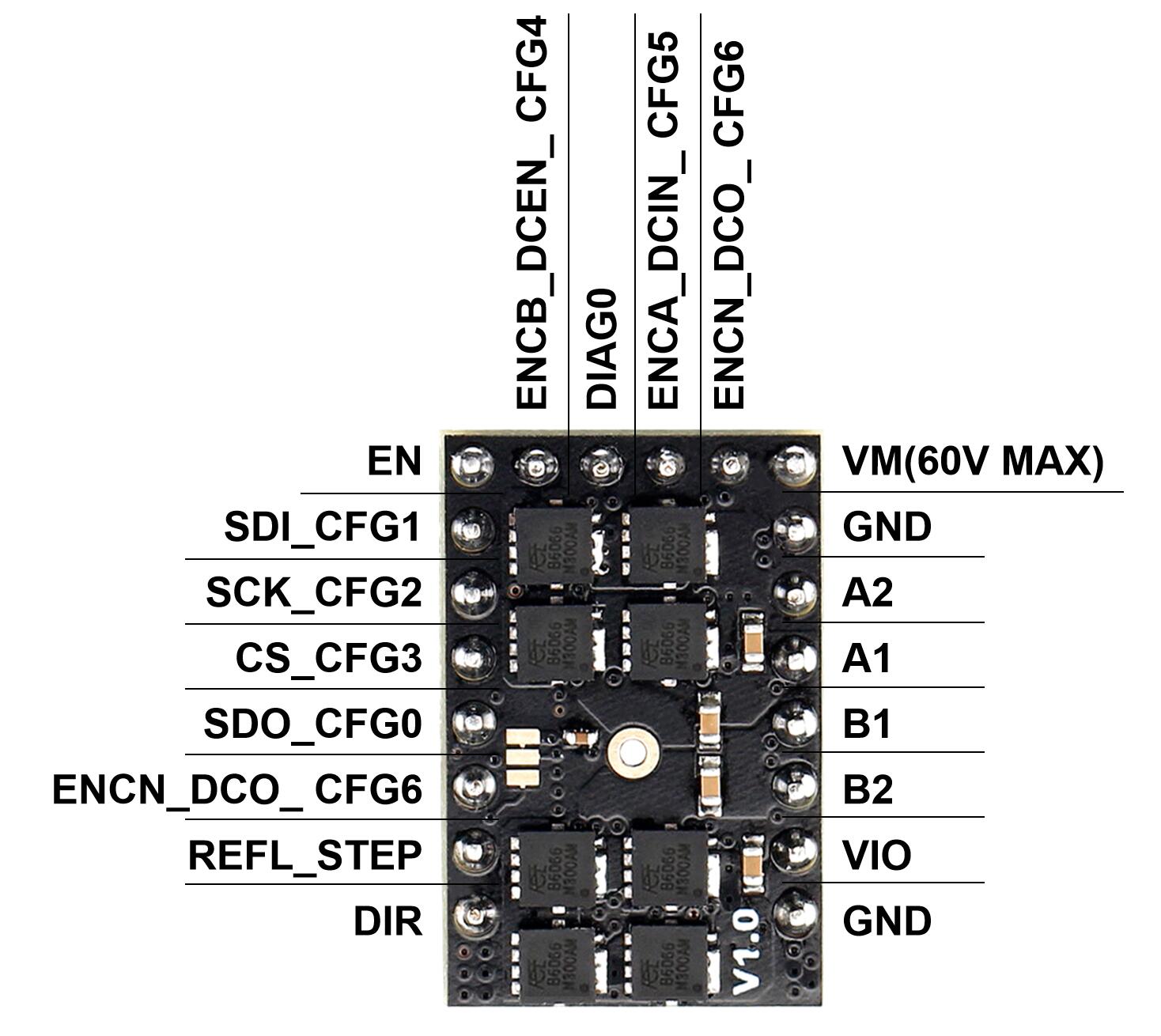
V1.x
V2.0
5.1 Pin Functions
Pin | Function |
|---|---|
Power Supply | |
GND | Ground |
VM | Motor Supply Voltage, Provide filtering capacity near pin with short loop to GND plane. Must be tied to the positive bridge supply voltage. |
VIO | 3.3V to 5V IO supply voltage for all digital pins. |
Motor Outputs | |
B1 | Motor Coil 1 |
B2 | Motor Coil 1 |
A1 | Motor Coil 2 |
A2 | Motor Coil 2 |
Control Inputs | |
REFL_STEP | STEP input when (SD_MODE=1).or left reference input (for internal ramp generator) |
DIR(REFR_DIR) | DIR input (SD_MODE=1).or right reference input (for internal ramp generator) |
TMC5160 | |
EN | Enable Motor inputs: GND=on, VIO=off |
SDI_CFG1 | SPI data input (SPI_MODE=1) or |
SCK_CFG2 | SPI serial clock input (SPI_MODE=1) or |
CSN_CFG3 | SPI chip select input (negative active) (SPI_MODE=1) or |
SDO_CFG0 | SPI data output (tristate) (SPI_MODE=1) or |
DIAG0 | Diagnostics output DIAG0. |
DIAG1 | Diagnostics output DIAG1. |
ENC-BENCBDCEN CFG4 | Encoder B-channel input (when using internal ramp generator) or |
ENC-AENCADCIN CFG5 | Encoder A-channel input (when using internal ramp generator) or |
ENC-NENCNDCO CFG6 | Encoder N-channel input (SD_MODE=0) or |
5.2 Configuration Instructions
⚠️ WarningIf you use 48V to power the VMOT of the module and 24V step-down to power the VIO, please make sure that 48V and 24V are turned on at the same time (that is, VMOT and VIO arrive at the same time). Otherwise, the drive module may burn out.5.2.1 Solder Jumper
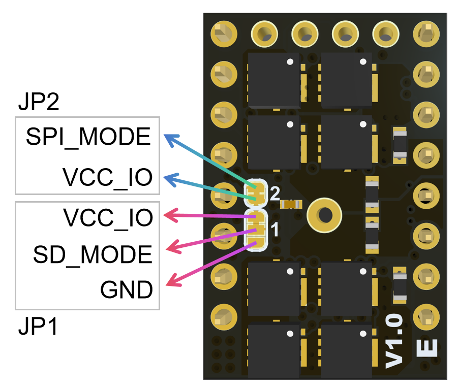
The working mode selection of QHV5160 depends on the level of Pin21 and Pin22 (integrated pull-down resistor).
In versions before V1.0E, Pin21 is fixed to high level and connected to VCC_IO, so the working mode is determined only by Pin22.
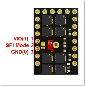
Pin22 is located on pad2 in the middle of the JP1 interface below. By default, it is connected to pad1, so according to the figure below, the default working mode is SPI mode. If you want to switch to independent mode, you need to cut the line between pad1 and pad2 with a knife (it is not easy to see, it is under the solder mask), and then connect pad2 and pad3 (weld).
In V1.0E, Pin21 sets a jumper pad, which is high by default and connected to VCC_IO. It can be switched to low level through operation, that is, connected to GND. The purpose is to facilitate some customers to enable the internal ramps generator.
JP2 is used to set SPI_MODE. The default connection is high level. After cutting, it is low level because the pin has a pull-down resistor.
JP1 is used to set SD_MODE. The default connection is with VCC_IO, which is high level. You can use a knife to cut the existing connection to set SD_MODE to low level.
V1.0
V1.0E
Pin22SPI_MODE | Pin21SD_MODE | Mode |
|---|---|---|
0 | 1 | Standalone Mode,Step-DIR Interface,CFG pins config:The STEP/DIR inputs control the driver , the chip is in standalone mode and pins have their CFG functions. |
1 | 1 | (Default)SPI Mode,Step-DIR Interface, config via SPI:The STEP/DIR inputs control the driver the SPI interface is enabled. Integrated pull down resistor. |
V2.0
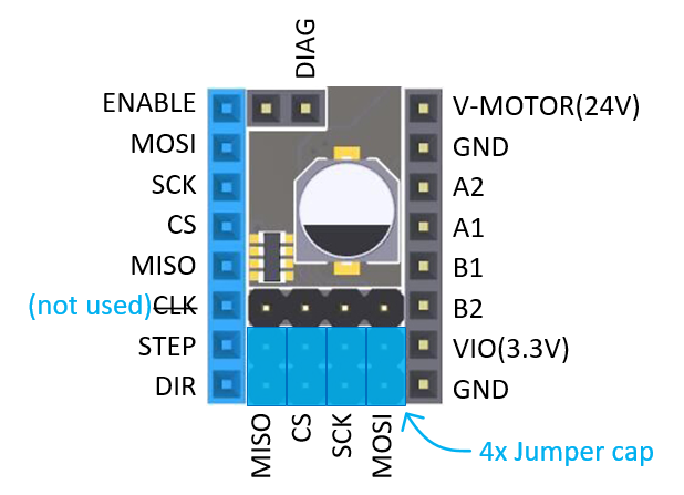
5.2.2 USE SPI mode on FYSETC Boards
5.2.3 Heatsink install
6. Firmware Guide
After you set the working mode according hardware guide section 5.2, you need to do firmware configuration. Follow the instruction below for different firmware Marlin and klipper configuration.
6.1 Marlin firmware
SPI Mode
#define *_DRIVER_TYPE TMC5160Standalone Mode
#define *_DRIVER_TYPE TMC5160_STANDALONE6.2 Klipper firmware
I take Spider2.x for example, add the content on your config file printer.cfg.
SPI Mode
##  Make sure to update below for your relevant driver (5160)
[tmc5160 stepper_x]
cs_pin: PE7
# Soft SPI
spi_software_mosi_pin: PE14
spi_software_miso_pin: PE13
spi_software_sclk_pin: PE12
interpolate: True
sense_resistor: 0.075
#diag0_pin: PB14 # For QHV5160 V1.x
diag1_pin: PB14 # For QHV5160 V2.0
run_current: 1.0
#hold_current: 0.5
#stealthchop_threshold: 0

##  Make sure to update below for your relevant driver (5160)
[tmc5160 stepper_y]
cs_pin: PE15
# Soft SPI
spi_software_mosi_pin: PE14
spi_software_miso_pin: PE13
spi_software_sclk_pin: PE12
interpolate: True
sense_resistor: 0.075
#diag0_pin: PB13   # For QHV5160 V1.x
diag1_pin: PB13   # For QHV5160 V2.0
run_current: 1.0
#hold_current: 0.5
#stealthchop_threshold: 0
Standalone Mode
Just delete the content you added for SPI mode.
6.3 Using The Motion Controller Via UART or SPI
The integrated 32-bit motion controller automatically drives the motor to target positions or accelerates to target velocities. All motion parameters can be changed on the fly. The motion
controller recalculates immediately. A minimum set of configuration data consists of acceleration and deceleration values and the maximum motion velocity. A start and stop velocity are supported as well as a second acceleration and deceleration setting. The integrated motion controller supports immediate reaction to mechanical reference switches and to the sensorless stall detection StallGuard2.
Benefits are:
- Flexible ramp programming
- Efficient use of motor torque for acceleration and deceleration allows higher machine throughput
- Immediate reaction to stop and stall conditions
7. Part List
- QHV5160 x1
- Aluminum Heatsink x1
- Thermally conductive silicone pad x1
8. Documentations
TMC5160 Chip Datasheet
Fysetc GitHub
9. Where to buy
10. Tech Support
Please submit any technical issues on our Discord Server
Updated on: 03/08/2026
Thank you!