TMC2130
Product Introduction
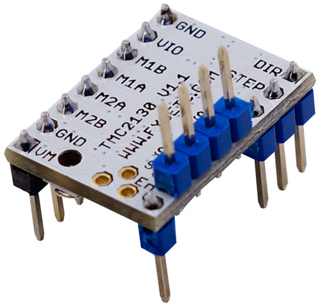
The TMC2130 provides an integrated motor driver solution for 3D-Printing, Cameras, Scanners and other automated equipment applications. The device has an integrated microstepping indexer, the sensorless stall detection technology StallGuard2™, the sensorless load dependent current control CoolStep™ and the completely noiseless current control mode StealthChop™ and is intended to drive a bipolar stepper motor.
Versions Difference
Versions | Difference |
|---|---|
V1.0 | The default is standalone mode. If you need SPI mode, you must config by yourself. |
V1.1 | SPI mode, SPI pin out (top), you must connect wires to your board and config the firmware for it, otherwise the stepper can't run. |
V1.2 | SPI mode, SPI&DIAG pin out (bottom), it's used for F6. |
Features
- SPI configuration interface (up to 4MHz)
- Up to 256 native microsteps (without interpolation)
- Reduce energy consumption by 75%
- High accuracy sensorless motor load detection
- High load driver will not lost step
- Automatic stealthChop and spreadCycle switchover depending on velocity
- Hardware compatible with StepStick and Pololu A4988 Stepper Driver
- Components on bottom PCB side for better heat emission
- Automatic standby current reduction
- stealthChop - for quiet operation and smooth motion
- spreadCycle - highly dynamic motor control chopper
Technical Specifications
Model | TMC2130 |
|---|---|
Interface | Step/Dir or SPI |
Configuration | CFG Pins or SPI |
Native Microsteps | up to 1/256 |
microPlyer Microsteps | 1/256 |
Logic Voltage (VIO) | 3-5V |
Motor Voltage (VM) | 5.5-46V |
Motor Phase Current max | 1.2A RMS, 2.5A Peak |
Internal V-Regulator | enabled |
RDSon | >=0.5 Ohm |
stealthChop (quiet) | yes |
spreadCycle | yes |
coolStep | yes |
stallGuard | yes |
dcStep | yes |
Pin Functions
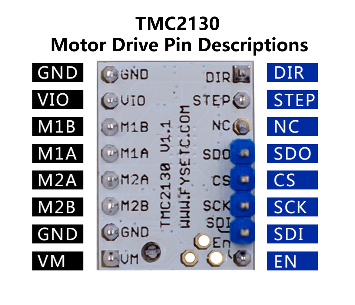
Pin | Function |
|---|---|
Power Supply | |
GND | Ground |
VM | Motor Supply Voltage |
VIO | Logic Supply Voltage |
Motor Outputs | |
M1A | Motor Coil 1 |
M1B | Motor Coil 1 |
M2A | Motor Coil 2 |
M2B | Motor Coil 2 |
Control Inputs | |
STEP | Step-Signal Input |
DIR | Direction-Signal Input |
TMC2130 (SPI_MODE=1) | |
EN | Enable Motor Outputs: GND=on, VIO=off, OPEN=Auto-Power-Down |
SDO/CFG0 | Serial Data Output (SPI) |
SDI/CFG1 | Serial Data Input (SPI) |
SCK/CFG2 | Serial Clock Input (SPI) |
CS/CFG3 | Chip Select Input (SPI) |
DCEN/CFG4 | dcStep Enable Input (GND=off) |
DCIN/CFG5 | dcStep Gating Input |
DIAG0 | Diagnostics Output 0 |
DIAG1 | Diagnostics Output 1 |
Interface Resources
SPI Mode
v1.0
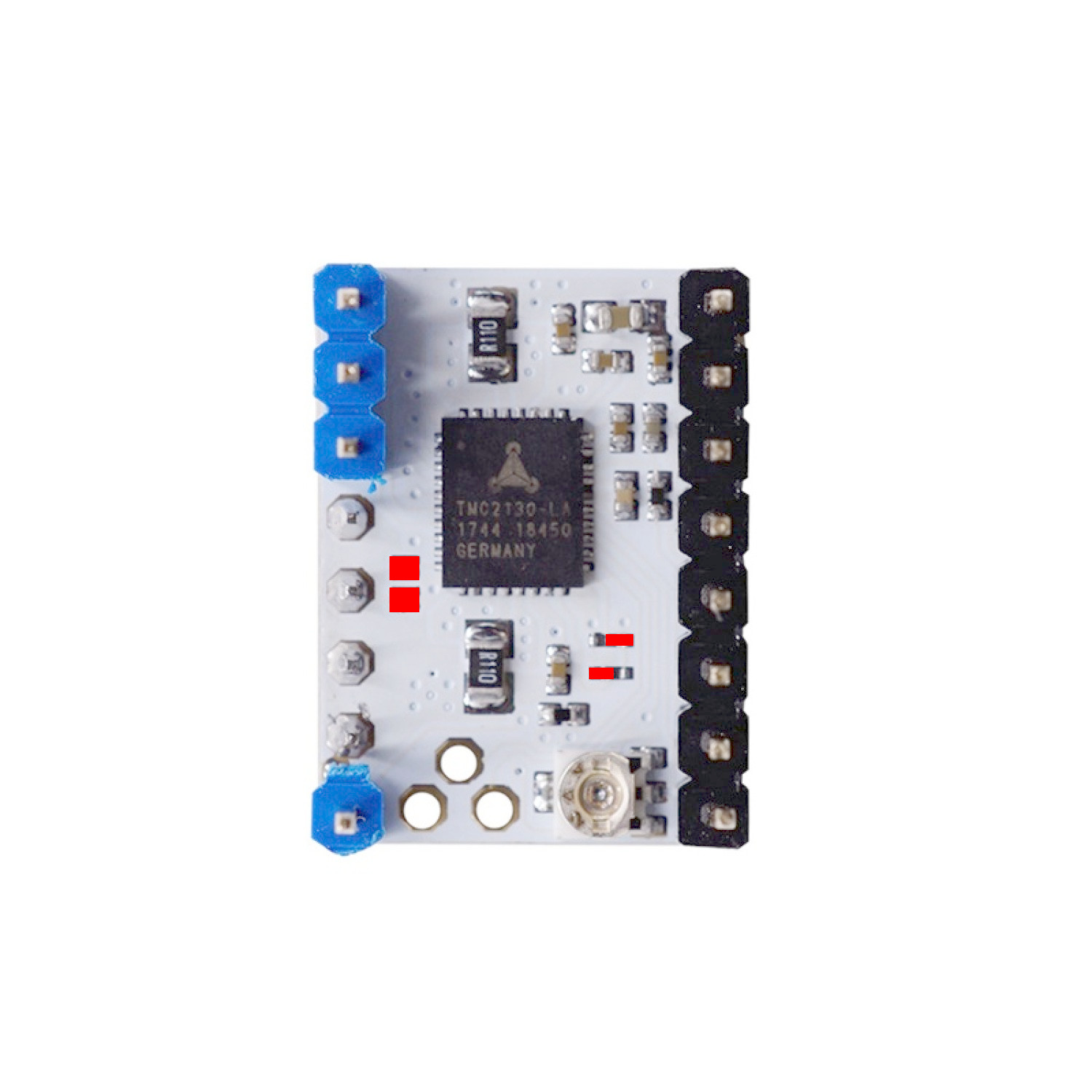
The FYSETC v1.0 drivers come pre-configured in standalone mode. To operate in SPI mode you need to modify three solder bridges on the driver PCB.
Some versions of the FYSETC v1.0 drivers come with a solder bridge left of the chip, some come with a bridging resistor. This connection needs to be opened for SPI connection to work. The two smaller bridges need to be configured as shown.
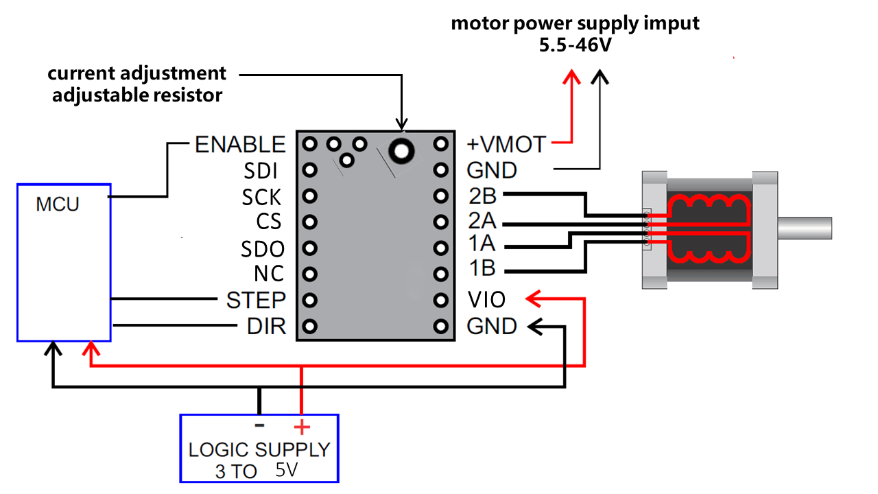
Wiring Diagram
Motor Current Setting
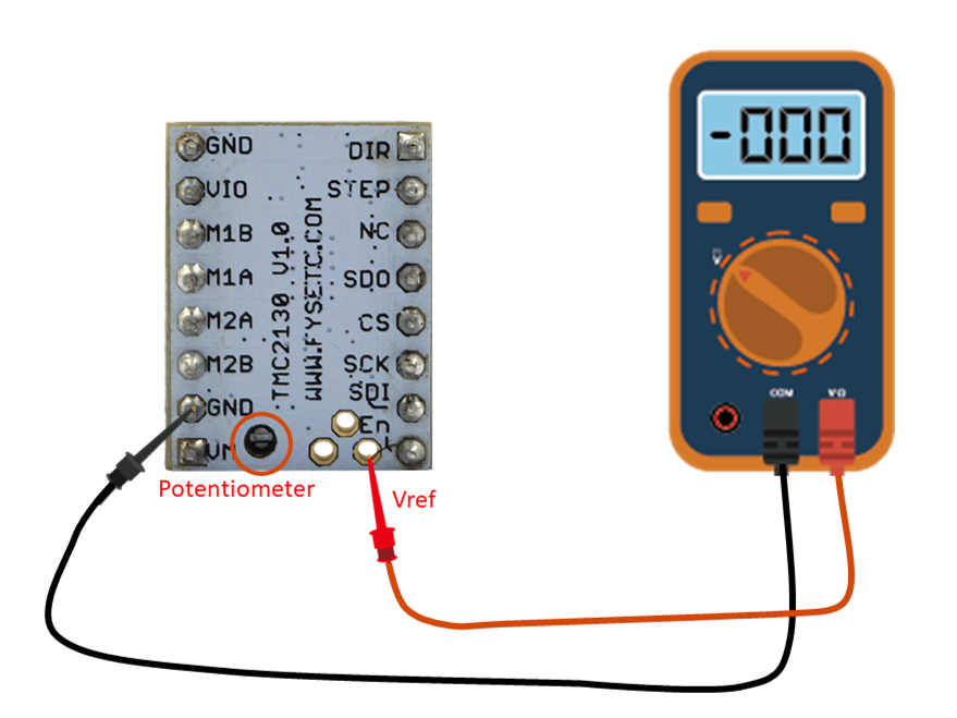
The best way to set the motor current is by measuring the voltage on the Vref pin (0…2.5V) and adjusting the voltage with the potentiometer. The maximum settable motor current is 1.77A RMS (0.11Ohm sense resistors), but the SilentStepSticks can only be used up to 1.2A RMS.
Irms = (Vref * 1.77A) / 2.5V = Vref * 0.71
Vref = (Irms * 2.5V) / 1.77A = Irms * 1.41 = Imax
Vref -> Voltage on Vref pin
Irms -> RMS (Root Mean Square) current per phase (Irms = Imax / 1.41)
Imax -> Maximum current per phase (Imax = Irms * 1.41)
RMS to Voltage Calculator
Reference Voltage (V) = RMS Current (A) × 1.41
Shop
Tech Support
Please join our Discord server - https://discord.gg/S9nZUCnDgm
Updated on: 03/08/2026
Thank you!