H36 Combo V2
Introduction
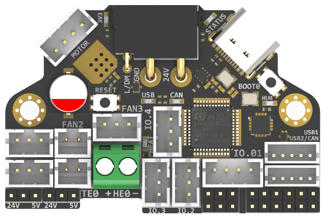
H36 Combo V2.0 is a newly designed high temperature tool board running Klipper firmware. Based on STM32G431CBT3, the maximum operating temperature can reach 125 degrees Celsius (CAN only). It also provides two communication methods: CANBUS and USB. The onboard USBHUB has up to two USB interfaces (or one CAN and one USB), which can be used to connect to the IDM Scanner Leveling Sensor camera, etc.
Version Notes
V2.0 (Currently Available)
- Change MCU to STM32G431CBT3
- Reassign pins
- Lead out the header pins for the SWD interface
- When the USB-C port is plugged in, it automatically switches to USB communication.
Features
- STM32G431CBT3 MCU, up to 125 degrees Celsius, supports Klipper Firmware
- 6-layer PCB design, all solid capacitors and tantalum capacitors, better heat dissipation
- Onboard RESET and BOOT0 buttons for easy firmware update
- Fan control/heating both use independent high-power MOS, safer and lower heat generation
- Onboard 5V@3A DC-DC, 5V peak load can reach 15W
- XT30 interface, custom cable comes with the board
- Onboard USB2.0 HUB, 3x USB2.0 interface (one of which is connected to MCU)
- Support CAN/USB2.0 connection
- Onboard TMC2209
- 3x 3pin Fans, 3x IO with level converter, 1x RGB,1x Heat, 1x thermistor,1x status LED
- ADXL345 Accelerometer onboard
- USB-C onboard for Firmware update
Applications
Print Head with NEMA14/36mm Motor
Hardware Specification
Function | H36 Combo V2.0 | H36 Combo V1 | SB Combo V2 | SB TH CAN V1.3 |
|---|---|---|---|---|
Microcontroller | STM32G431CBT3 | STM32G0B1T3 | STM32F072CBT6 | STM32F072CBT6 |
Accelerometer | ADXL345 | ADXL345 | ADXL345 | ADXL345 |
USB Port | 2 + 1 (For MCU) , Powered by CH334P | 2 + 1 (For MCU) , Powered by CH334P | 2 + 1 (For MCU) + 1(on aux board), Powered by CH334P | 1 |
CANBUS | 1 + 1 (For MCU) | 1 + 1 (For MCU) | 1 + 1 (For MCU) | 1 |
Fan | 4 (1x2Pin, 3x3Pin) | 4 (1x2Pin, 3x3Pin) | 3+2 (on aux board) | 2 |
Heating output | 1 | 1 | 1 | 1 |
Temperature measurement | 1 (PH2.0 connector) + 1 (on board thermistor) | 1 (PH2.0 connector) + 1 (on board thermistor) | 1 (PH2.0 connector) + 1 (on board thermistor) | 1(PH2.0 connector) |
Voltage monitoring | 5V, 24V | 5V, 24V | 5V, 24V | |
Motor drive | TMC2209 | TMC2209 | TMC2209 | TMC2209 |
Signal input and output | 5 (PH2.0) + 7 (pin header) | 5 (PH2.0) + 7 (pin header) | 3 | 3 |
RGB light strip control | default 2, up to 5 | default 2, up to 5 | 1 + 1 (on aux board) | 1 |
Aux Board support | No | No | Yes | No |
Onboard mounting nut | No | No | Yes | No |
Operating limits
WainingThe following values are tested at room temperature of 25°C. Please do not keep the highest peak value running for a long time!Please do a good job of cooling the board in a higher temperature environment.Stepper drivers | Up to 2.0A peak current |
|---|---|
Mosfets Outputs | HE0 up to 5A Max, Fan up to 0.5A each |
Input power voltage | 11V to 24V for VIN up to 10A Max |
Inputs/Outputs | Signal 20ma maximum, RGB power supply 1.5A total maximum |
5V and 3.3V current limit | 5V@3A Max,3.3V@0.8A Max |
Physical Connections
Pin Out
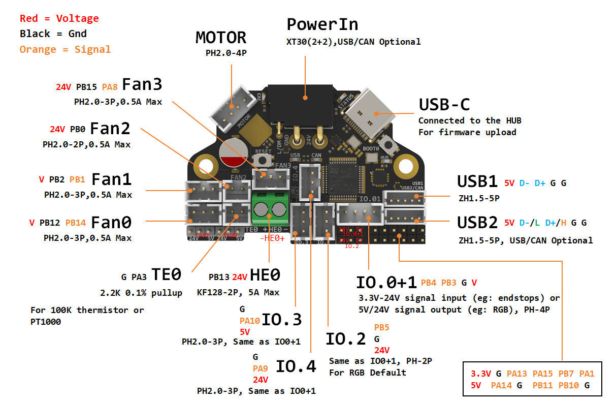
Thanks to Esoterical for creating this image.
IO.0: PB3
IO.1: PB4
IO.2: PB5
IO.3/RGB0: PA10
IO.4/RGB1: PA9
# IO.0 - IO.4 with level conversion (pull-up), it can be used as 5V/24V level input and output!

FAN0: PB12
FAN0_TACH: PB14
FAN1: PB2
FAN1_TACH: PB1
FAN2: PB0
FAN3: PB15
FAN3_TACH: PA8

Heat: PB13
Thermistor (2.2k pull up): PA3

Driver_EN: PC14
Driver_DIR: PC15
Driver_STEP: PB9
Driver_UART: PB6
Driver_DIAG: PA13

ADXL345
spi_bus: spi1
adxl345_cs_pin: PA4
adxl345_spi_software_sclk_pin: PA5
adxl345_spi_software_miso_pin: PA6
adxl345_spi_software_mosi_pin: PA7

CAN_RX: PA11
CAN_TX: PA12

Thermistor next to TMC2209 (4.7k pull up) : PA0

CAN USB switch: PA2
# logic Low = COM to A PORT  CANBUS
# Logic High = COM to B PORT  USB
Extra Pins Function
Pin Number | Pin name | Pin type | I/O structure | Alternate function | Additional functions |
|---|---|---|---|---|---|
37 | PA13 | I/O | FT_f | SWDIO-JTMS,TIM16_CH1N,I2C1_SCL,IR_OUT,USART3_CTS,TIM4_CH3,SAI1_SD_B,EVENTOUT | |
38 | PA14 | I/O | FT_f | SWCLK-JTCK,LPTIM1_OUT,I2C1_SDA,TIM8_CH2,TIM1_BKIN,USART2_TX,SAI1_FS_B,EVENTOUT | |
39 | PA15 | I/O | FT_f | JTDI,TIM2_CH1, TIM8_CH1,I2C1_SCL, SPI1_NSS,SPI3_NSS/I2S3_WS,USART2_RX,UART4_RTS_DE,TIM1_BKIN, TIM2_ETR,EVENTOUT | |
PB7 | I/O | FT_f | TIM17_CH1N,TIM4_CH2,I2C1_SDA,TIM8_BKIN,USART1_RX,COMP3_OUT,TIM3_CH4,LPTIM1_IN2,UART4_CTS,EVENTOUT | ||
9 | PA1 | I/O | TT_a | RTC_REFIN,TIM2_CH2,USART2_RTS_DE,TIM15_CH1N,EVENTOUT | ADC12_IN2,COMP1_INP,OPAMP1_VINP,OPAMP3_VINP |
22 | PB10 | I/O | TT_a | TIM2_CH3,USART3_TX,LPUART1_RX,TIM1_BKIN,SAI1_SCK_A,EVENTOUT | OPAMP3_VINM |
25 | PB11 | I/O | FT_a | TIM2_CH4,USART3_RX,LPUART1_TX,EVENTOUT | ADC12_IN14 |
For more info, Please refer to STM32G431CBT3 datasheet
How to Use Hardware I2C
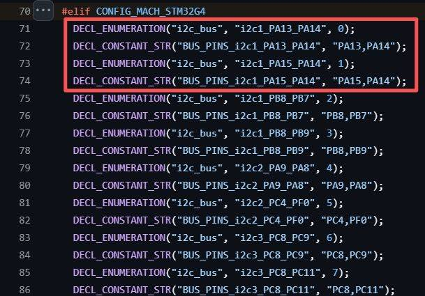
- Based on the G431 header files within Klipper, you should select PA13/PA14 or PA14/PA15 as the hardware I2C interface to connect your external devices—such as the I2C Eddy.
- According to feedback from some customers, it appears that PA14/PA15 is easier to use.
- You can also get more information from the Klipper documentation:
https://www.klipper3d.org/Config\_Reference.html?h=i2c#common-i2c-settings
Description Of Connections
IO.0 and IO.1 are located in the same connector and can be used as XY endstops, and IO.2 can be used as a probe. In addition, IO.0 - IO.5 have level conversion (with pull-up resistors) , IO.01, IO.2 have voltage selectors (5V or 24V) pin header, IO.3 IO.4 have voltage selectors (5V or 24V) pads. All the IOs can be used as inputs or outputs, such as RGB ,Servo, Endstops, and can be configured according to your other needs.
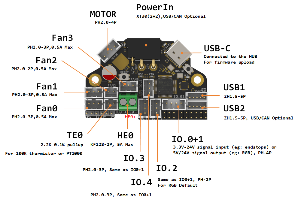
Connector | Pin | Default function | Altermate |
|---|---|---|---|
Power Input | USB (PA11,PA12) | Power and communication input, USB 2.0 and CANBUS are optional, Determined by the level of PA2. | |
Fan0 | FAN0: PB12 | Mosfet Output, For 2/3 pins Fan, Default voltage = Depending on voltage selector. (Header voltage selector) | |
Fan1 | FAN1: PB2 | Mosfet Output, For 2/3 pins Fan, Default voltage = Depending on voltage selector.(Header voltage selector) | |
Fan2 | PB0 | Mosfet Output, For 2 pins Fan, Default voltage = VIN.(Pad voltage selector) | |
Fan3 | FAN3: PB15 | Mosfet Output, For 2/3 pins Fan, Default voltage = VIN.(Pad voltage selector) | |
IO.0+1 | PB3, PB4 | Digital Input, For X Y endstop, Micro switch or Hall**(Header voltage selector)** | Digital Output |
IO.2 | PB5 | Digital Input, For Z probe, Proximity switch or Klicky, etc.(Header voltage selector) | Digital Output |
IO.3/RGB0 | PA10 | 5V Digital Output, 5V power supply default, For 5V WS2812/SK6812 RGB/Servo**(Pad voltage selector)** | Digital Input |
IO.4/RGB1 | PA9 | 5V Digital Output, 24V power supply default, For 24V WS2812/SK6812 RGB/Servo**(Pad voltage selector)** | Digital Input |
USB1 | USB2.0 | J2 | |
USB2/CAN | USB2.0 or CANBUS 2.0, USB 2.0 and CANBUS are optional,Determined by the level of PA2. | J1 | |
TE0 | PA3 | ADC input, 2.2K pull-up, head temperature measure | |
HE0 | PB13 | Mosfet Output, Heating rod control, 5A Max | |
MOTOR | For two-phase stepper motor, | ||
USB1, USB-C connector | Connected to the CH334PHUB chip, up to 4 USB2.0 devices (MCU/USB1/USB2/USB3) |
Connecting Fans
3 Wire Fans
3 wire fans can be connected by following the Pin Out above.
4 Wire Fans
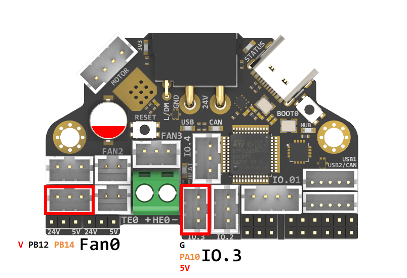
This info is based on the Creality K1 4020 blower fan, thank you to user EAZY for their work on this setup.4 wire fans require the use of 2 connectors to enable the control on the PWM wire and to monitor the TACH wire.
H36 Combo V2 Connections
Fan0:
24V > V
GND > PB12
TACH > PB14
IO.3:
PWM > PA10
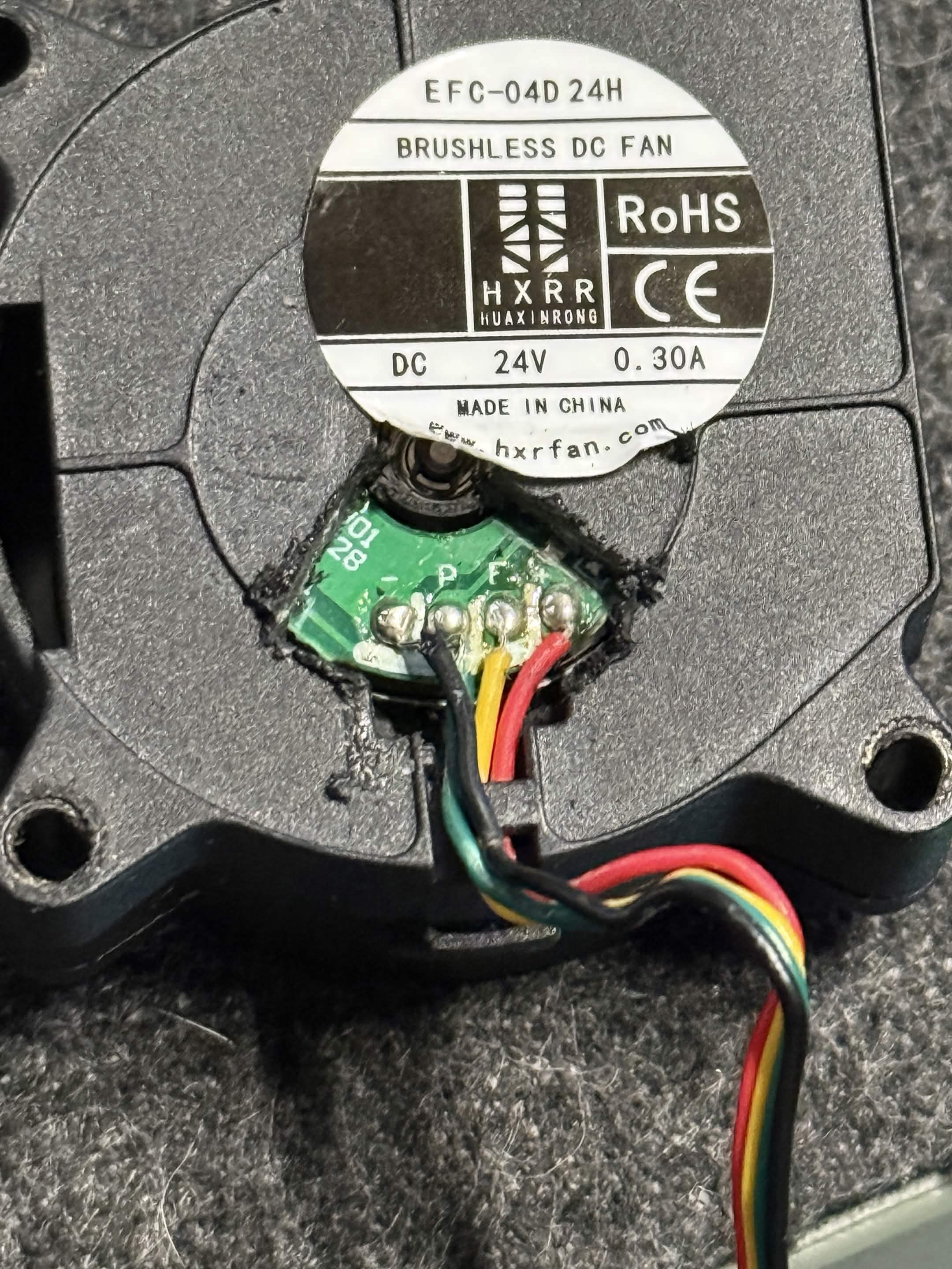
Creality 4020 Blower Fan Pin Out
Red > 24V
Black > GND
Green > PWM
Yellow > TACH
Configuration
[output_pin fan0_power] #keeps 24V on for part cooling fan as GND(PB12) is a mosfet
pin: H36_combo:PB12
value: 1
shutdown_value: 0

[fan] # Part cooling fan PWM
pin: H36_combo:PA10
max_power: 1.0
shutdown_speed: 0.0
cycle_time: 0.00004   # 25kHz for 4-wire PWM fan
hardware_pwm: false
kick_start_time: 0.5
tachometer_pin: ^H36_combo:PB14
USB / CAN Selection
XT30 and USB2/CAN both use CAN to communicate refer to the instructions below for connecting the H36 via CAN.
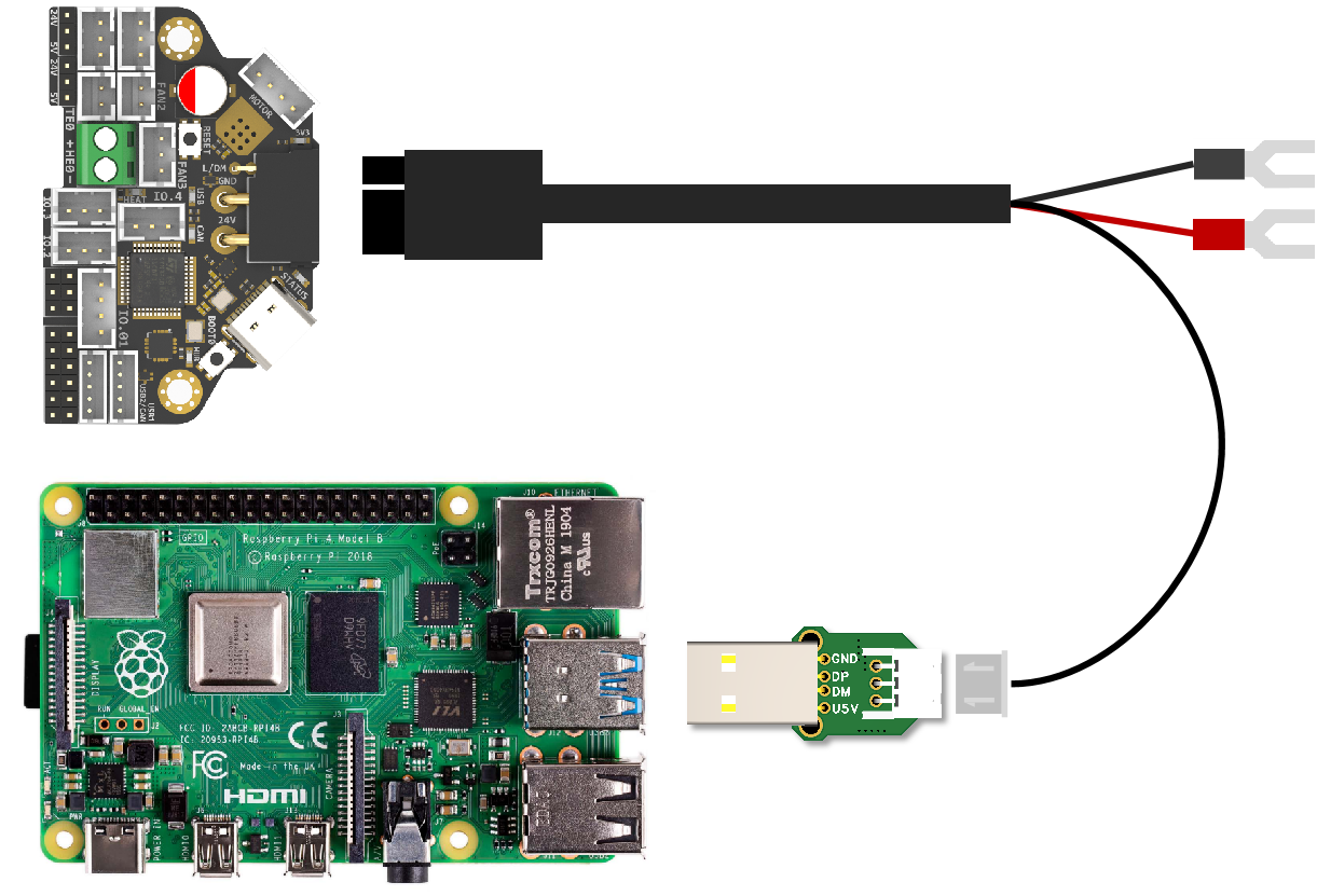
XT30 and USB2/CAN both use USB to communicate refer to the instructions below for connecting the H36 via USB.
Header Jumpers
IO.0+1 , IO.2 , Fan0 , Fan1 can select the power supply voltage through the jumper cap.
As shown in the figure, the two pins on the left are connected together for 24V, and the two pins on the right are connected together for 5V.

LED Indicators
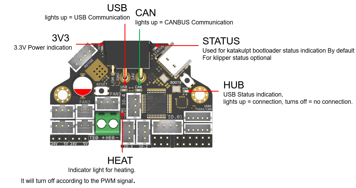
LED name | Indicate | Remark |
|---|---|---|
3V3 | Lights up: Power supply OK. | Red |
HUB | Lights up: The USB has at least one connection. | Red |
STATUS | When using katakulpt | Red |
HEAT | Lights up or flashes according to the heating PWM | Red |
USB | USB communication Indicate, use "PA2" at the config menu | Red |
CAN | CAN communication Indicate, use "!PA2" at the config menu | Green |
Communication
Connection To Pi
H36 combo V2 can be connected to Pi via USB or CANBUS. Select by PA2, refer to USB / CAN selection.
Via CAN
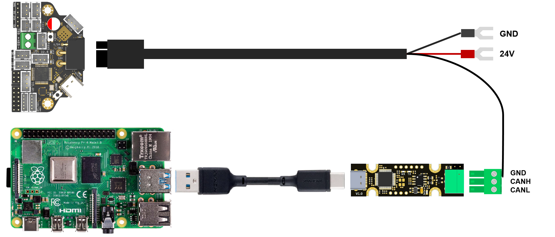
Since the Raspberry Pi does not have a CANBUS interface, it is usually connected only after the CANBUS interface is expanded through an expansion chip. Commonly used ones include the MCP2518 SPI to CAN module (CanHat), USB to CAN module (eg: UCAN), Klipper USB to CAN Bridge Mode, and a Linux host computer with a native CAN interface (eg: CM68).
Via USB
When using USB connection, you can use the adapter board we provide to directly connect to the USB interface of PI.
Firmware Guide
Firmware Configuration And Compilation
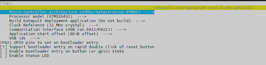
With Katapult Bootloader
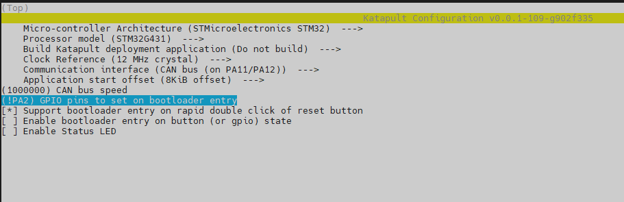
If you need to use a bootloader, we recommend using katapult. The following is not configured for reference:
For katapult use, refer to: https://github.com/Arksine/katapult
shell
cd ~/katapult
make menuconfig
make flash FLASH_DEVICE=0483:df11
USB
CAN
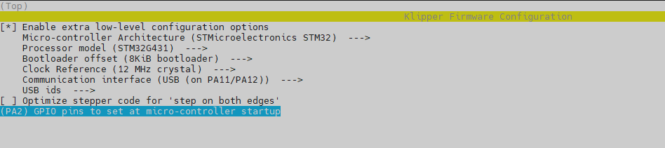
cd ~/klipper
make menuconfig
make
cd ~/katapult/scripts
#when using CAN communication
python3 flashtool.py -i can0 -f ~/klipper/out/klipper.bin -u <uuid>
#when using USB communication
python3 flashtool.py -d <serial device> -b <baud_rate> -f ~/klipper/out/klipper.bin
USB
CAN
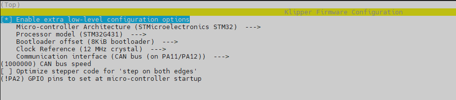
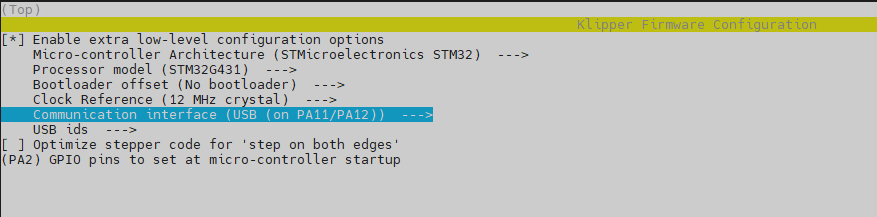
Klipper With No Bootloader
H36 uses the bootloader-free mode by default, and the configuration is as follows:
USB
CAN
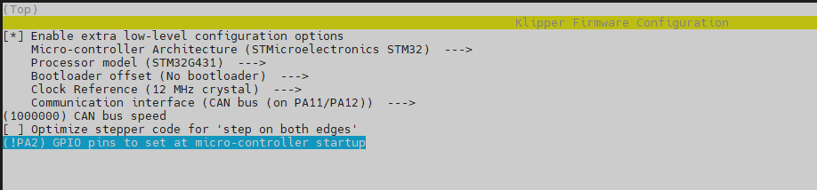
Firmware Upload
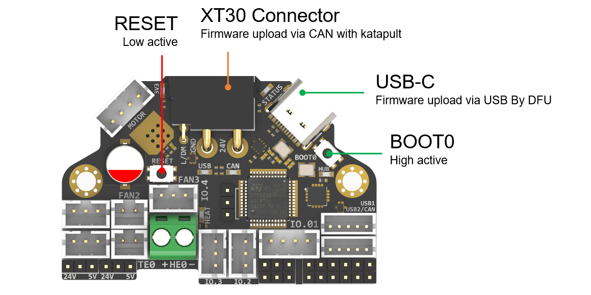
Before executing the following commands, you need to enter DFU mode before you can compile and burn the firmware. As shown in the figure above,
- press and hold BOOT0,
- then press the RESET button for one second,
- then release RESET,
- wait for 3 seconds,
- and release BOOT0.
Use " lsusb" to check if a DFU device appears. If yes, upload firmware. If no, repeat the above steps.
make flash FLASH_DEVICE=0483:df11under katapult Klipper uploading, Please refer to:
https://github.com/Arksine/katapult?tab=readme-ov-file#uploading-klipper
Attachments And Other Documents
2D,3D , SCH and config template file, please go to our github:
https://github.com/FYSETC/H36\_Combo\_V2
Where To Buy
Technical Support Channel
Updated on: 03/08/2026
Thank you!