H42_V1.0
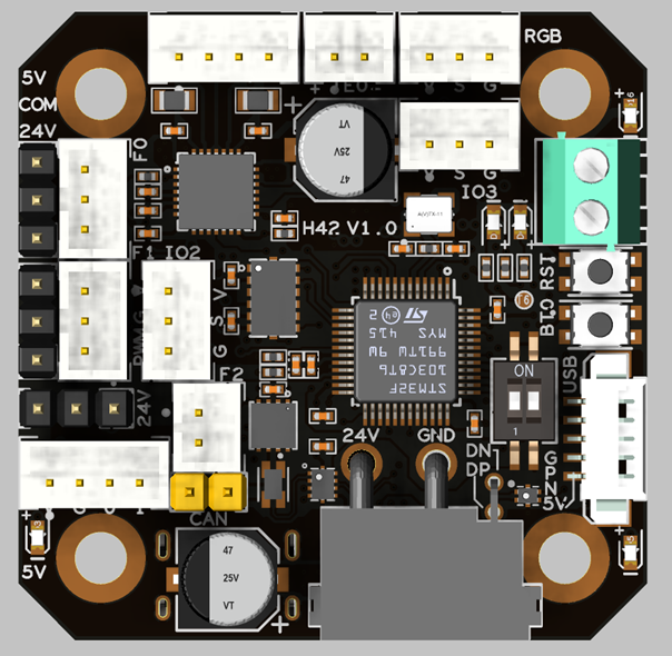
Since there is no 125 degree Celsius USB-HUB chip, the 125 degree Celsius operating environment is limited to CANBUS mode;
Klipper currently does not support 125 degree Celsius accelerometers, so the 125 degree Celsius operating environment does not include accelerometers. The default version of H42 is ADXL345, which has a maximum operating temperature of 85 degrees Celsius. The 105 degree Celsius ADXL345-EP version is optional, but it is more expensive
Introduction
H42_V1.0 is a toolboard running Klipper firmware. Based on the STM32G431CBT3, it supports a maximum operating temperature of 125°C (CAN only).
It also provides two communication methods: CANBUS and USB. The onboard USB hub supports USB interfaces for connecting USB devices, and it features an inductive displacement sensor interface based on the LDC1612.
Featrues
- STM32G431CBT3 MCU, supports Klipper Firmware
- 6-layer PCB design, all solid capacitors and tantalum capacitors
- Onboard CAN/USB switch
- Onboard RESET and BOOT0 buttons for easy firmware update
- Fan control/heating both use independent high-power MOS, safer and lower heat generation
- Onboard 5V@3A DC-DC, 5V peak load can reach 15W
- XT30 interface, custom cable comes with the board
- Onboard USB2.0 HUB, 2x USB2.0 interface (one of which is connected to MCU)
- Support CAN / USB2.0 connection
- Onboard TMC2209
- 2x 3pin + 1x 2pin Fans, 4x IO with level converter, 1x RGB,1x Heat, 1x thermistor,1x status LED
- LDC1612 Eddy Current Sensor
- ADXL345 Accelerometer onboard
- USB-C onboard for Firmware update
Application
- Voron AfterBurner Head
- NEMA 17 Stepper Motors Head
Hardware specification
Function | Specifications |
|---|---|
Microcontroller | STM32G431CBT6 |
Accelerometer | ADXL345 |
USB Port | 1 + 1 (For STM32G431) + 1(on aux board), Powered by CH334P |
Fan | 2+1 (2x 3pin + 1x 2pin) |
Heating output | 1 |
Temperature measuremen | 1 (PH2.0 connector) + 1 (on board thermistor) |
Motor drive | TMC2209 |
Signal input and output | 4 |
RGB light strip control | 1 |
Onboard mounting nut | Yes |
Operating limits
WainingThe following values are tested at room temperature of 25°C. Please do not keep the highest peak value running for a long time!
Please do a good job of cooling the board in a higher temperature environment.
Stepper drivers | Up to 2.0A peak current |
|---|---|
Mosfets Outputs | HE0 up to 5A , Fan up to 2.5A each |
Input power voltage | 11V to 24V for VIN up to 10A |
Inputs/Outputs | Signal 20ma maximum, RGB 2.5A total maximum |
Physical Connections
Pin Out
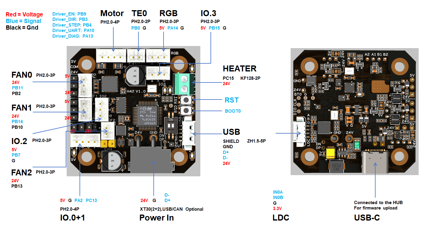
Pin Definitions
IO.0: PA2
IO.1: PC13
IO.2: PB7
IO.3: PB15

FAN0: PB2
FAN0_TACH: PB11
FAN1: PB10
FAN1_TACH: PB14
FAN2: PB13

RGB: PA14

HEATER: PC15
Thermistor (2.2k pull up): PB0

Driver_EN: PB9
Driver_DIR: PB3
Driver_STEP: PB4
Driver_UART: PA10
Driver_DIAG: PA13

ADXL345
spi_bus: spi1
adxl345_cs_pin: PA0
adxl345_spi_software_sck_pin: PA5
adxl345_spi_software_moso_pin: PA6
adxl345_spi_software_misi_pin: PA7

LDC1612
SDA: PA8
SCL: PA9

CAN_RX: PA11
CAN_TX: PA12

Thermistor next to TMC2209 (4.7k pull up) : PB12
Description of Connections:
IO.0 and IO.1 are located in the same connector and can be used as XY endstops,
Connector | Pin | Default function | Altermate |
|---|---|---|---|
Power Input | USB/CANBUS (PA11,PA12) | Power and communication input, USB 2.0 and CANBUS are optional. | Digital I/O |
FAN0 | FAN0:PB2, FAN0_TACH:PB11 | Mosfet Output, For 2/3 pins Fan, Default voltage = Depending on voltage selector. (Header voltage selector) | Digital Output |
FAN1 | FAN1:PB10, FAN1_TACH:PB14 | Mosfet Output, For 2/3 pins Fan, Default voltage = Depending on voltage selector. (Header voltage selector) | Digital Output |
FAN2 | PB13 | Mosfet Output, For 2-pin fans,Default voltage = Depending on voltage selector. (Header voltage selector) | Digital Output |
IO.0+1 | IO.0:PA2 IO.1:PC13 | Digital Input, For X Y endstop, Micro switch or Hall (Pad voltage selector) | Digital Output |
IO.2 | PB7 | Digital Input, For Z probe, Proximity switch or Klicky, etc. (Pad voltage selector) | |
IO.3 | PB15 | Digital Input, (Pad voltage selector) | |
RGB | PA14 | Digital Input, (Pad voltage selector) | |
HEATER | PC15 | Mosfet Output, Heating rod control, 5A Max | |
TE0 | PB0 | ADC input, 2.2K pull-up, head temperature measure | |
MOTOR | For two-phase stepper motor |
LED indications:
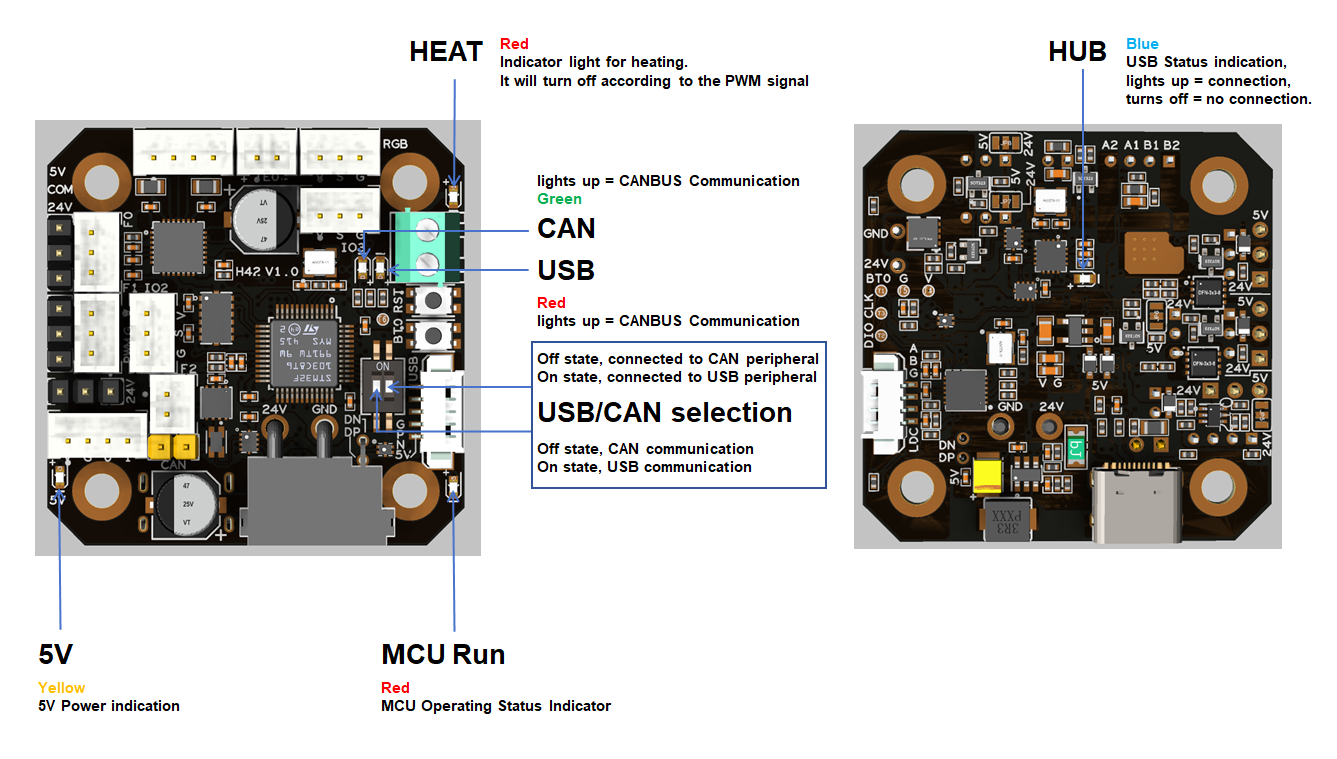
LED Name | Indicate | Remark |
|---|---|---|
5V | On: Power supply normal. Off: Power supply failure. The 5V output is derived from 24V via a DC-DC converter. | Yellow |
HUB | Lights up: The USB has at least one connection.Turns off: The USB has no connection. | Blue |
MCU Run | The MCU is in an active state. | Red |
HEAT | Lights up or flashes according to the heating PWM | Red |
USB | USB communication Indicate,DIP switch On | Red |
CAN | CAN communication Indicate,DIP switch off | Green |
USB / CAN Switcher
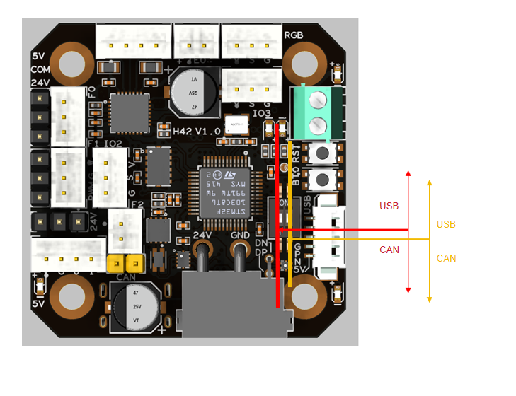
As shown in the figure, the red-marked toggle switch is responsible for the input CAN/USB switching, which is located on the XT30 connector; the yellow-marked toggle switch is responsible for the CAN/USB switching at the connector marked as USB2 (MX1.25-5P).
Jumpers
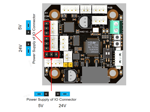
fan can select the power supply voltage through the jumper cap. As shown in the figure, the two pins on the left are connected together for 5V, and the two pins on the right are connected together for 24V.
Communication
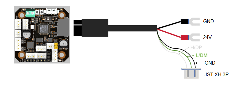
Via CAN
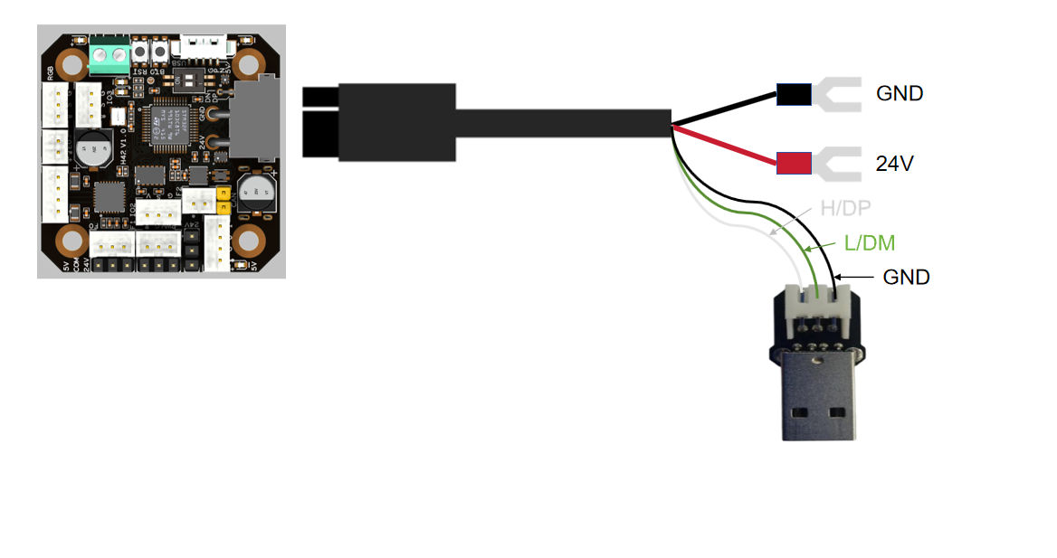
Via USB
Connections
Fans
Temperature Sensor
Thermistor
PT1000
Motor
Endstops
RGB
Others
FIrmware Guide
Firmware configuration and compilation
Katapult Bootloader
Thanks to the great Katapult project for making Klipper firmware updates much easier. If you are willing to invest some time in reading Katapult's documentation, then I recommend you use it, otherwise just use the no booloader mode!
For more information about katapult, please refer to https://github.com/Arksine/katapult
The following is a simple guide, but please check the configuration options carefully!
cd katapult
make menuconfig
make flash FLASH_DEVICE=0483:df11
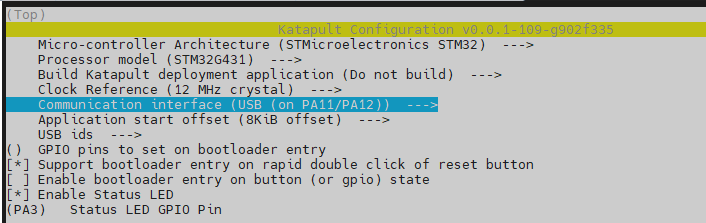
katapult is configured in USB mode
katapult is configured in CANBUS mode
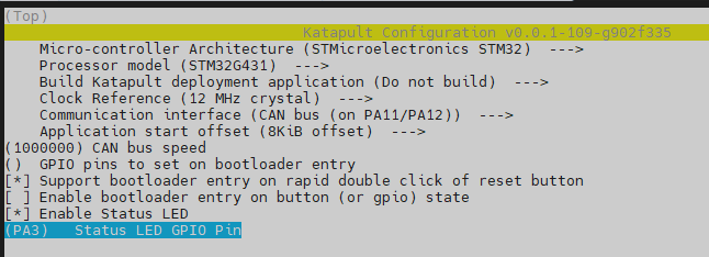
Klipper Firmware Config
Using katapult bootloader
CANBUS communication mode
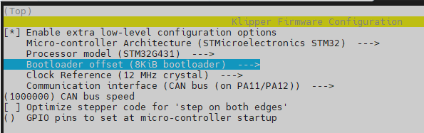
USB communication mode
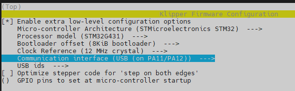
Using no bootloader
CANBUS communication mode
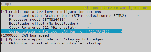
USB communication mode
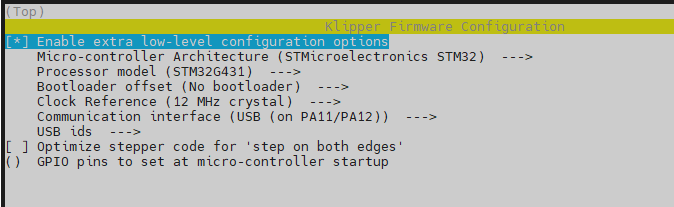
Firmware upload
DFU Mode
firmware flashing can only be performed after entering DFU mode.
How to get in DFU mode:
- hold BT0 button for 2 seconds
- Hold RST button for 2 seconds
- Release the RST button
- wait 2seconds
- Release the BT0 button
"lsusb" check if get in DFU mode
No Bootloader Mode or Upload the Katapult Bootloader
Command:
cd ~/klipper
make flash FLASH_DEVICE=0483:df11
Use the Katapult Bootloader Uploading Klipper
- Make sure the klipper service stopped.
- Build Klipper with CAN support and with the a bootloader offset matching that of the "application offset" in Katapult.
- Enter the bootloader. Katapult automatically enters the bootloader if it detects that the application area of flash is empty. When upgrading from a currently flashed version of Klipper the flashtool.py script will command USB and CANBus devices to enter the bootloader. Note that "USB to CAN bridge devices" and "UART" devices cannot be auto-detected. If the device is not in bootloader mode it is necessary to first manually request the bootloader with the -r option, then rerun the script without -r to perform the upload. Devices running software other than Klipper will need to request the bootloader with their own method.
- Run the flash script: For CAN Devices:
cd ~/katapult/scripts
python3 flashtool.py -i can0 -f ~/klipper/out/klipper.bin -u
Replace with the appropriate uuid for your can device. If the device has not been previously flashed with Klipper, it is possible to query the bootloader for the UUID:
flashtool.py -i can0 -q
Example
- Make sure the katapult bootloader has been burned
- Double-click the RESET button to enter the bootloder, the sign is that the STATUS LED will flash
- Use the command (reafer to https://www.klipper3d.org/CANBUS.html)
~/klippy-env/bin/python ~/klipper/scripts/canbus_query.py can0
Find can uuid
- Use the uuid to update the firmware
NOTEpython3 flashtool.py -i can0 -f ~/klipper/out/klipper.bin -u 02479ee3301f
A query should only be performed when a single can node is on the network. Attempting to query multiple nodes may result in transmission errors that can force a node into a "bus off" state. When a node enters "bus off" it becomes unresponsive. The node must be reset to recover.
For USB/UART devices: Before flashing, make sure pyserial is installed. The command required for installation depends on the the linux distribution. Debian and Ubuntu based distros can run the following commands:
sudo apt update
sudo apt install python3-serial
python3 flashtool.py -d -b
Replace the the path to the USB/UART device you wish to flash. The is only necessary for UART devices, and defaults to 250000 baud if omitted.
!!! example Example
- Make sure the katapult bootloader has been burned
- Double-click the RESET button to enter the bootloder, the sign is that the STATUS LED will flash
- Use the command
ls /dev/serial/by-id
Find can mcu id
- Use the id to update the firmware
python3 flashtool.py -d /dev/serial/by-id/the_id_you_get
FAQ
Attachments and others
- 安装示例:支架(STL)
- 散热:推荐的通风方式
- 温度:MCU,驱动,电源
How to buy
淘宝,速卖通,亚马逊,官网
Technical Support Channel
FB / Discord / Forum
Updated on: 03/08/2026
Thank you!