Catalyst.K ToolHead
Introduction
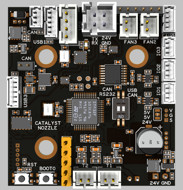
Catalyst.K ToolHead is a compact Klipper toolboard with a footprint of only 47 mm × 44 mm, designed to be mounted close to the printhead or extruder. It is powered by an STM32G431CBT6 32‑bit MCU and supports multiple communication modes, including USB and CAN / RS‑232, which can be switched via an on‑board physical button.
The board integrates a TMC2209 stepper motor driver, an ADXL345 3‑axis accelerometer, multiple fan and temperature inputs, as well as BL‑Touch and hotend heater control. This greatly simplifies toolhead wiring, reduces cable bundle weight on moving parts, and improves overall reliability and serviceability of the printer.
Features
- Compact toolboard design: 47 mm × 44 mm, mounted directly near the printhead or extruder to greatly simplify wiring.
- STM32G431 MCU: 32‑bit high‑performance controller optimized for Klipper multi‑MCU setups.
- Multiple communication modes: Supports USB, CAN, and RS‑232, switchable via on‑board button.
- On‑board USB hub: Provides 3× USB ports and 1× CAN port for easy host and expansion connectivity.
- Integrated TMC2209: On‑board 24V‑powered TMC2209 stepper driver for silent, precise extruder control.
- Built‑in ADXL345: On‑board 3‑axis accelerometer for Klipper input shaping and resonance testing.
- Stable power outputs: 24V input (max. 28V) with on‑board 5V@3A and 3.3V@0.8A rails.
- Rich IO and fan interfaces: 4 level‑shifted IO pins, 4 fan outputs (2×2‑wire with selectable 5V/24V, 1×3‑wire, 1×4‑wire).
- Complete sensing and actuator interfaces: 3 temperature inputs, 1 BL‑Touch connector, 1 hotend heater output up to 2.5A.
- Easy debugging: On‑board BOOT0 and RESET buttons for quick flashing and debugging.
Applications
- Used as a Klipper toolhead board for extruder/printhead control, providing local motor drive, temperature control, fan control, and acceleration measurement on the toolhead to greatly simplify the printer’s wiring.
- Suitable for mid‑ to high‑end FDM 3D printers that require integrated TMC2209, ADXL345, BL‑Touch, and multiple fan/temperature interfaces, both for upgrading existing machines and for new printer designs.
- Applicable in multi‑toolhead, multi‑nozzle, or remote‑extrusion setups as a distributed toolboard node, connected to the Klipper host system via CAN or USB /RS‑232 to build flexible multi‑MCU motion control architectures.
Hardware Specifications
Item | Specification |
|---|---|
Product name | Catalyst.K ToolHead |
Board size | 47 mm × 44 mm |
MCU | STM32G431CBT6, 32‑bit ARM Cortex‑M4 |
Communication modes | USB, CAN, RS‑232 (selectable via on‑board button) |
Input voltage | 24 V DC (max. 28 V) |
On‑board power rails | 5 V @ 3 A, 3.3 V @ 0.8 A |
Stepper driver | On‑board TMC2209, 24 V supply |
Accelerometer | On‑board ADXL345 3‑axis accelerometer |
Level‑shifted IO | 4× IO with voltage translators (selectable by pads) |
Fan outputs | 4 digital fan outputs: 2×2‑wire (5V/24V jumper‑selectable), 1×3‑wire, 1× 4‑wire |
Temperature inputs | 3× temperature sensor inputs |
Probe interface | 1× BL‑Touch connector |
Heater output | 1× hotend heater output, up to 2.5 A |
On‑board buttons | BOOT0 button, RESET button |
Physical Connections
Pin Out
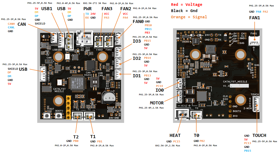
IO.0: PC14
IO.1: PB13
IO.2: PB14
IO.3: PB15

FAN0_PWCTL: PB3
FAN0_PWM: PB10
FAN0_TACH: PB11

FAN1: PA2
FAN1_TACH: PA8
FAN2: PA4
FAN3: PA3

Heat: PC15
Thermistor (4.7k pull up): PB2
Thermistor (4.7k pull up): PB1
Thermistor (4.7k pull up): PB0
Thermistor next to TMC2209 (4.7k pull up) : PB12

Driver_EN: PB9
Driver_DIR: PB6
Driver_STEP: PB7
Driver_UART: PA15
Driver_DIAG: PA13

ADXL345
spi_bus: spi1
adxl345_cs_pin: PA0
adxl345_spi_software_sclk_pin: PA5
adxl345_spi_software_miso_pin: PA6
adxl345_spi_software_mosi_pin: PA7

USB_DM/CAN_RX: PA11
USB_DP/CAN_TX: PA12

Signal_PWM: PC13
Description Of Connections
Connector | Pin | Default function | Altermate |
|---|---|---|---|
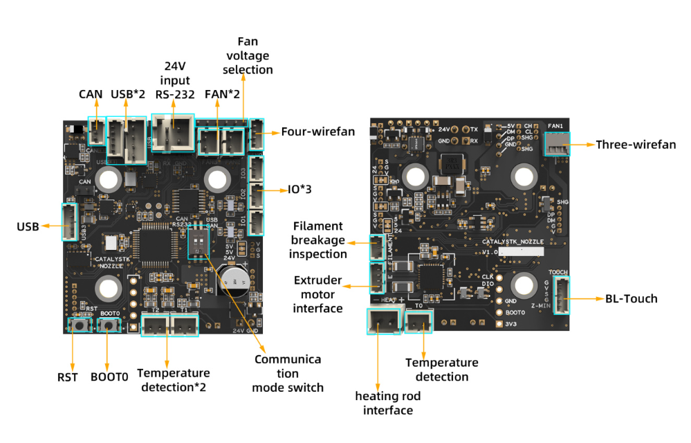
Power Input | RS-232 (PA9,PA10) | Power and communication input, RS-232 and CANBUS are optional, which can be switched via an on‑board physical button. | I/O |
Fan0 | FAN0_PWR: PB3 | Mosfet Output, For 4 pins Fan, voltage = 24V | |
Fan1 | FAN1: PA2 | Mosfet Output, For 3 pins Fan, Default voltage = 24V | |
Fan2 | PA4 | Mosfet Output, For 2 pins Fan, Default voltage = Depending on voltage selector. (Header voltage selector) | |
Fan3 | PA3 | Mosfet Output, For 2 pins Fan, Default voltage = Depending on voltage selector. (Header voltage selector) | |
IO.0 | PC14 | Digital Input, For endstop, Micro switch or Hall (Pad voltage selector) | Digital Output |
IO.1 | PB13 | Digital Input, For endstop, Micro switch or Hall (Pad voltage selector) | Digital Output |
IO.2 | PB14 | Digital Input, For endstop, Micro switch or Hall (Pad voltage selector) | Digital Output |
IO.3 | PB15 | Digital Input, For endstop, Micro switch or Hall (Pad voltage selector) | Digital Output |
TOUCH | PWM:PC13 | 5V Digital Output, Digital Input, For Z probe, Proximity switch or Klicky, etc. (Pad voltage selector) | Digital Input |
T0 | PB2 | ADC input, 4.7K pull-up, temperature measure | Analog signal Input |
T1 | PB1 | ADC input, 4.7K pull-up, temperature measure | Analog signal Input |
T2 | PB0 | ADC input, 4.7K pull-up, temperature measure | Analog signal Input |
HEAT | PC15 | Mosfet Output, Heating rod control, 2.5A Max | |
MOTOR | For two-phase stepper motor,24V | ||
USB1, USB3 | Connected to the CH334P HUB chip, up to 4 USB2.0 devices (USB/USB1/MCU/USB3) |
Connection
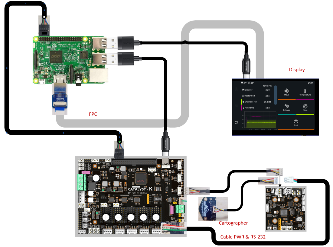
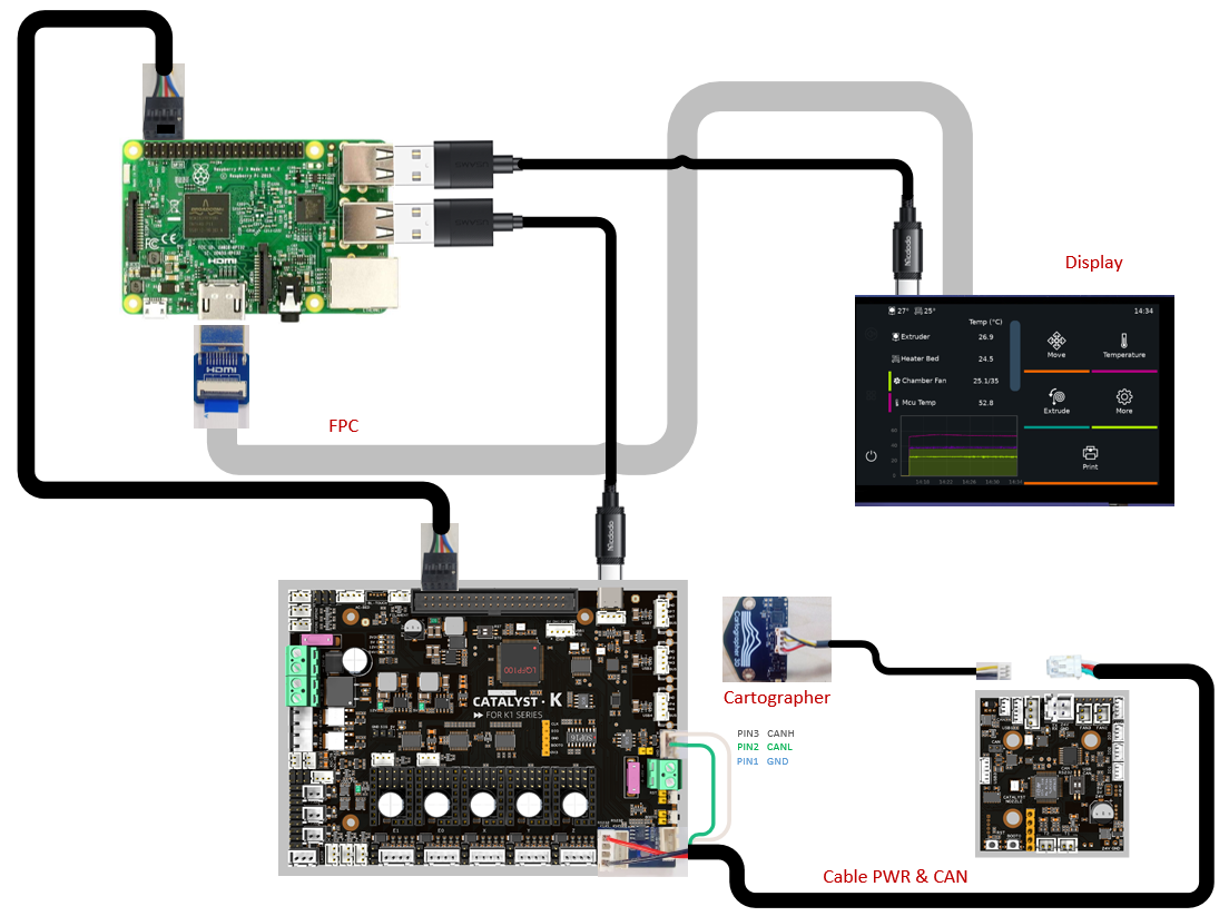
Simply connect our motherboard (CATALYST.K) to the Raspberry Pi's header power port and USB port using a power cable and data cable (USB to Type-C), respectively, as shown in the diagram below. No additional power supply is required for the Raspberry Pi, as our motherboard provides 5V@6A power output—more than sufficient to ensure the Raspberry Pi operates normally.
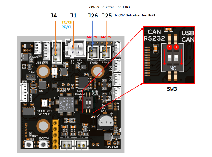
USB Communication Mode (Recommend)
- Connect the RS-232 connector (XH2.54-4) on the main board (CATALYST.K) to the power connector (J1) on the tool board (Catalyst.K ToolHead)
- Connect the USB connector (USB4) on the main board (CATALYST.K) to the connector (J4) on the tool board (Catalyst.K ToolHead).
- Connect J23 on the tool board (Catalyst.K ToolHead) to the Cartographer.
- Set PIN 1 on the DIP switch (WS3) on the Catalyst.K ToolHead to ON and PIN 2 to ON. This completes the hardware connections.
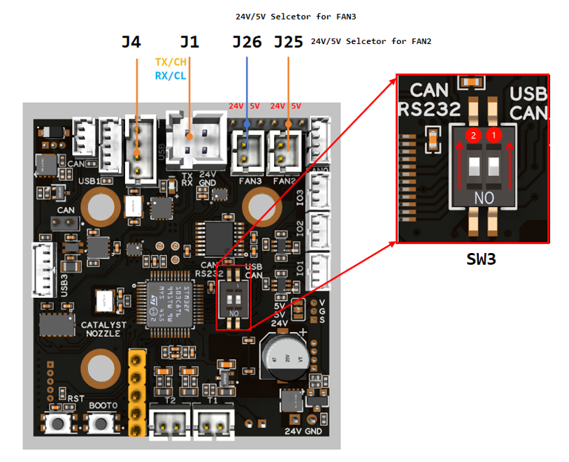
RS-232 Communication Mode (Unsupported)
- Connect the RS-232 connector (XH2.54-4) on the main board (CATALYST.K) to the power connector (J1) on the tool board (Catalyst.K ToolHead)
- Connect the USB connector (USB4) on the main board (CATALYST.K) to the connector (J4) on the tool board (Catalyst.K ToolHead).
- Connect J23 on the tool board (Catalyst.K ToolHead) to the Cartographer.
- Set PIN 1 on the DIP switch (WS3) on the Catalyst.K ToolHead to OFF and PIN 2 to OFF. This completes the hardware connections.
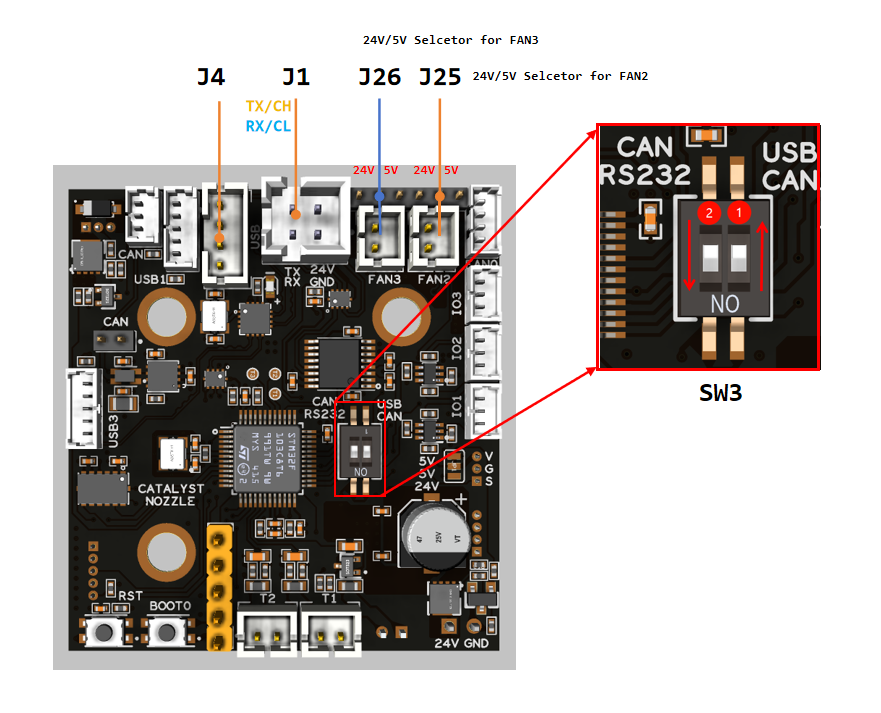
CAN Communication Mode
- Connect the RS-232 connector (XH2.54-4) on the main board (CATALYST.K) to the power terminal (J1) on the tool board (Catalyst.K ToolHead), and strip the white and green data wires from the cable harness to connect them to PIN 1 and PIN 2 of the CAN (XH2.54-3) connector on the main board (CATALYST.K), respectively.
- Connect J21 on the Catalyst.K ToolHead to the Cartographer.
- Set PIN 1 of the DIP switch (WS3) on the Catalyst.K ToolHead to OFF and PIN 2 to ON. This completes the hardware connections.
Header Jumpers
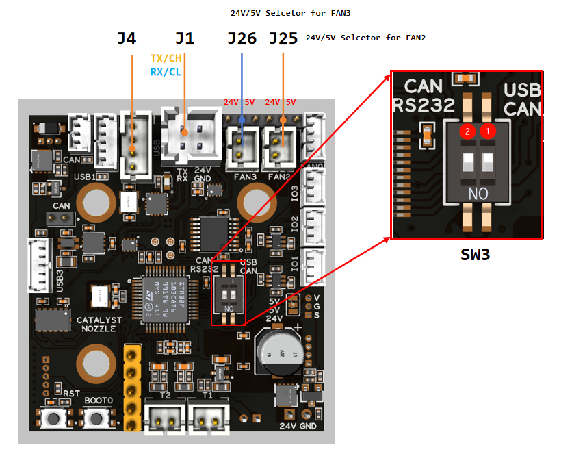
Fan2 , Fan3 can select the power supply voltage through the jumper cap.
As shown in the figure, the two pins on the left are connected together for 24V, and the two pins on the right are connected together for 5V.
Firmware Guide
Firmware Configuration
Klipper With No Bootloader (Recommend)
Login to the host computer using tool such as MobaXterm or PuTTY via SSH, and execute the following command to open the firmware configuration tool.
cd ~/klipper
make menuconfig
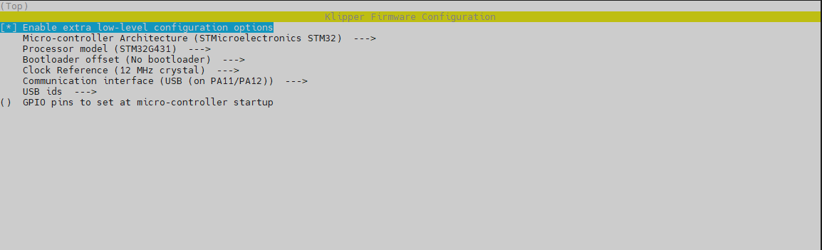
The recommended mode is USB mode and the configuration is as follows.
USB (Recommend)
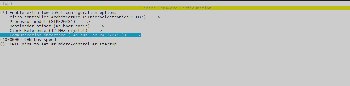
CAN
SERIAL (Unsupported)
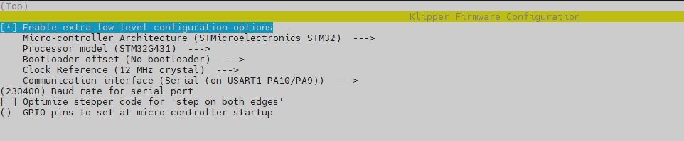
Complete the configuration shown in the reference image , then save the configuration and exit the configuration tool.
If using Katapult, please refer to:https://github.com/Arksine/katapult?tab=readme-ov-file#uploading-klipperFirmware Upload
Waining- Before flashing the firmware, connect the Raspberry Pi and CATALYST.K using a USB cable,refer to the connection diagram USB Communication Mode.
- Before flashing the firmware, must complete the firmware configuration,refer to the Firmware Configuration
- If the firmware is configured for CAN mode, please re-verify the wiring connections and DIP switch after the firmware flashing process is complete, refer to the connection diagram CAN Communication Mode.
- If the firmware is configured for RS-232 mode, please re-verify the wiring connections and DIP switch after the firmware flashing process is complete, refer to the connection diagram RS-232 Communication Mode.
DFU mode
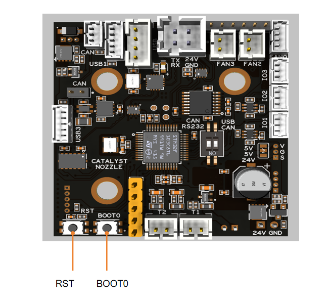
You need to enter DFU mode before you can compile and burn the firmware. As shown in the figure above,
- press and hold BOOT0,
- press the RESET button for one second,
- release RESET,
- wait for 3 seconds,
- release BOOT0.
Use the command 'lsusb' to check if a DFU device is detected. If it appears, proceed with uploading the firmware. If not, repeat the previous steps.
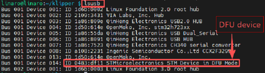
Firmware flash
After the device is in DFU mode, execute the following commands to compile and flash the program.
make flash FLASH_DEVICE=0483:df11After the burning process is complete, it will display "File downloaded successfully".
ID Search
Warning- The ID can only be recognized after the firmware flashing process is complete. If it has not yet finished, please refer to the Firmware Upload section.
- If Mainsail or KlipperScreen indicates that it cannot connect to the MCU, you must modify the MCU ID before attempting to reconnect.
- Open your browser, enter the IP address of the host computer in the address bar, for example, my host computer's IP is 192.168.0.179, just enter it and press Enter.
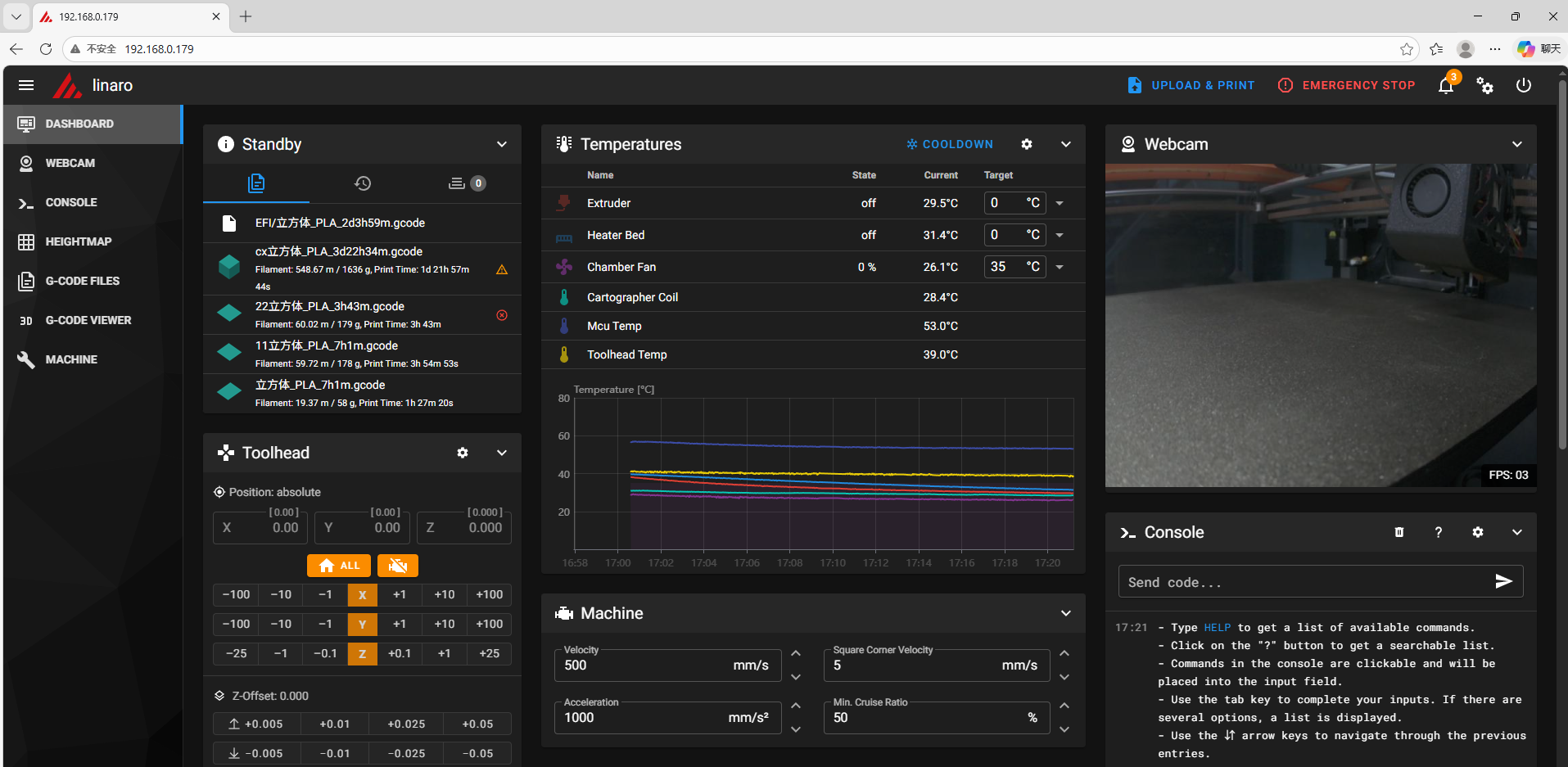
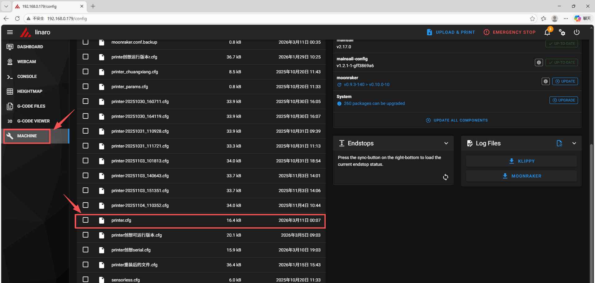
- Open the web interface of the host computer, and find "Machine" in the configuration options on the left sidebar. Click to open the printer.cfg file.
- Click the DEVICES button in the upper right corner.
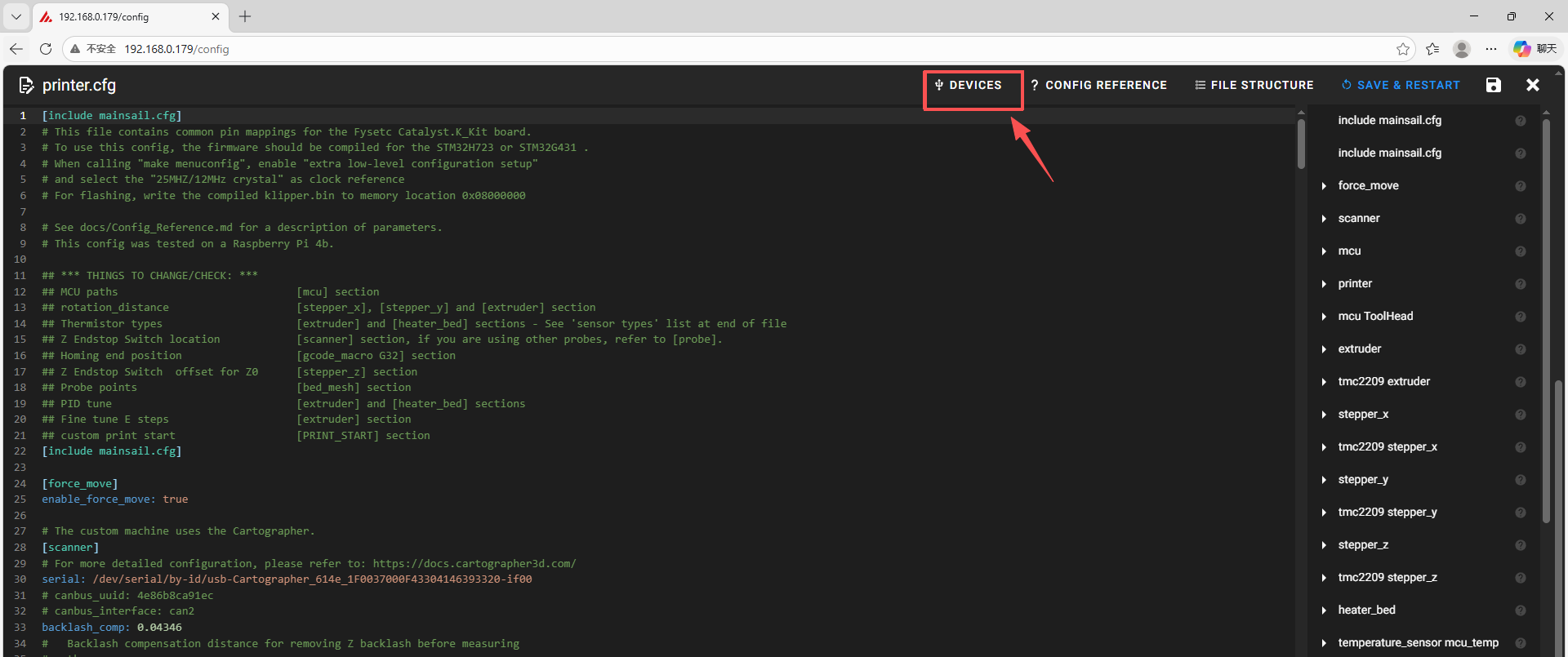
If DEVICES cannot be found, you need to reinstall Mainsail.
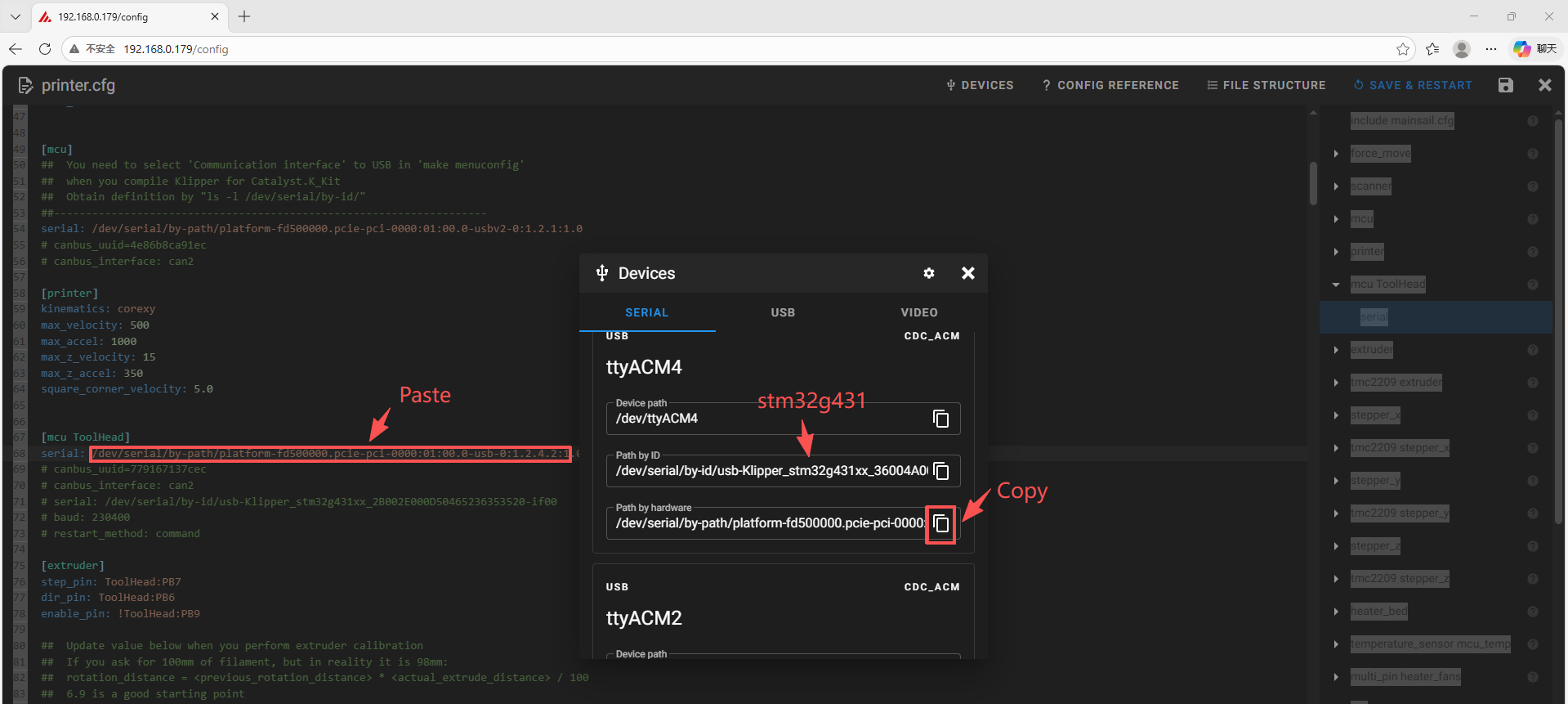
- After selecting the communication method, click refresh. Copy the ID by clicking the arrow, then paste it into the [mcu ToolHead] section of printer.cfg.
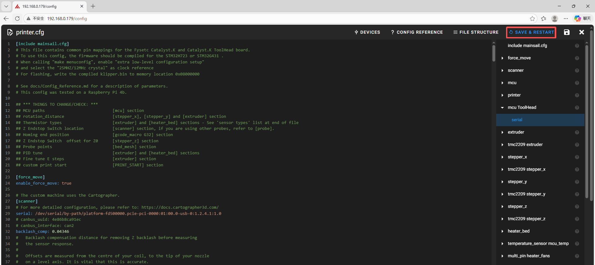
- Click the save and restart button in the upper right corner.
Attachments And Other Documents
2D,3D , SCH and config template file, please go to our github:
https://github.com/FYSETC/Catalyst.K\_Kit
Where To Buy
Technical Support Channel
support@fysetc.com
https://discord.gg/yYVx98gCDW
Updated on: 03/08/2026
Thank you!