NanoDLP_Shield_V1.1
Product Introduction
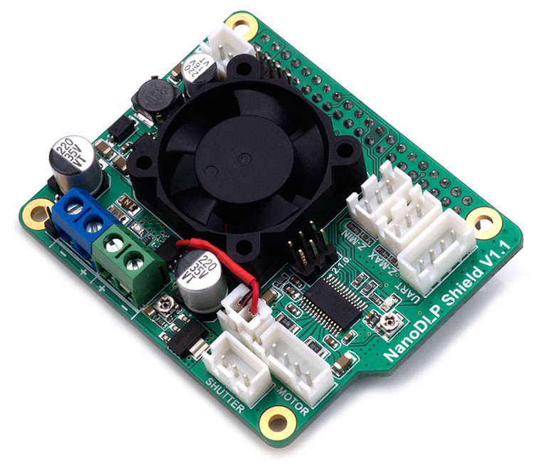
This expansion board is designed for the Raspberry Pi 3B which is used for SLA/DLP 3D printers running NanoDLP . The board contains a 9-28V to 5V circuit that provides a maximum of 3A and other interfaces required by NanoDLP. See the instructions below.
Features
- 9V-28V to 5V@3A Buck Converter
- DRV8825 Stepper Driver
- 12V Fans (cooling the Pi)
- 2X Endstops
- Controled MOS for ext LED driver
- I2C Connector for LCD1602
- Uart Connector for Touch Screen
- Shutter support
- 5V OUT Connector for ext Board
Application
- For NanoDLP software on Raspberry Pi
Specifications
Board Name | NanoDLP Shield |
|---|---|
License | CPL V2 |
Latest Version | V1.1 |
Fixed Port | 1X 12V(Same as input) and 5V |
Controlled Port | 1X 12V(Same as input) |
Endstops | Z-min /Z-max |
I2C | 1X PinHeader-4P |
Serial port | 1X XH2.54-4P |
Stepper driver | 1X DRV8825@2.5A max/32 microsteps max |
Input | 9V-28V |
Output | 5V@3A max, 9-28V@3A max |
Interface Resources
Interface Layout
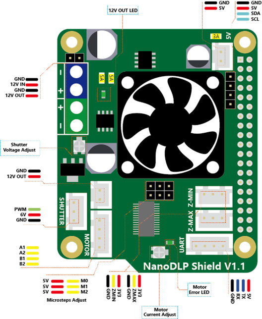
Micro-stepping
Shorted = 1, Open = 0 .
MS2 | MS1 | MS0 | Microsteps |
|---|---|---|---|
0 | 0 | 0 | Full step (2-phase excitation) with 71% current |
0 | 0 | 1 | 1/2 step (1-2 phase excitation) |
0 | 1 | 0 | 1/4 step (W1-2 phase excitation) |
0 | 1 | 1 | 8 microsteps/step |
1 | 0 | 0 | 16 microsteps/step |
1 | 0 | 1 | 32 microsteps/step |
1 | 1 | 0 | 32 microsteps/step |
1 | 1 | 1 | 32 microsteps/step |
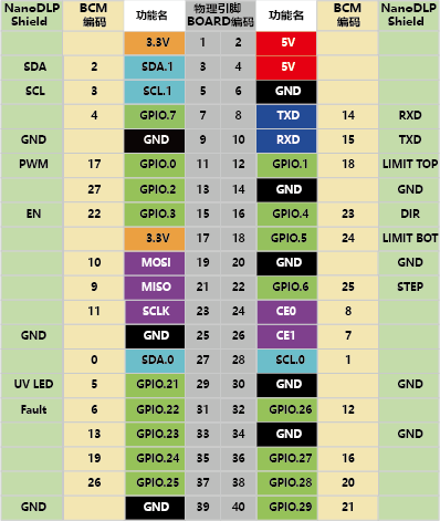
Pin Definition
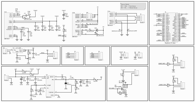
Schematic
Wiring Diagram
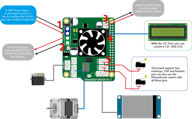
- 9-28V Power Input, if you need connect a fan to cooling the UVLED you can connect it here too.
- For UVLED Input, you can ON/OFF the UVLED by Controlling the Output.
- HDMI to MIPI Board or other device which need 5V power.
- With the I2C Port, you can connet a I2C 1602LCD.
- The board support two endstops, TOP and bottom, you can also use the Photoelectric switch with all three pins.
Shop
Tech Support
Please submit any technical issue into our forum
Updated on: 03/08/2026
Thank you!